Improvements of braking systems

A technology of brake disc and brake pad, which is applied in the direction of brake actuator, application, harvester, etc., can solve the problems of complex mechanism and high manufacturing cost

Active Publication Date: 2007-02-14
ROBERT BOSCH GMBH
View PDF0 Cites 11 Cited by
  • Summary
  • Abstract
  • Description
  • Claims
  • Application Information

AI Technical Summary

Problems solved by technology

These mechanisms, consisting of many moving parts, are generally complex
Manufacturing costs are also high

Method used


Image

  • Improvements of braking systems
  • Improvements of braking systems
  • Improvements of braking systems

Examples


Embodiment Construction

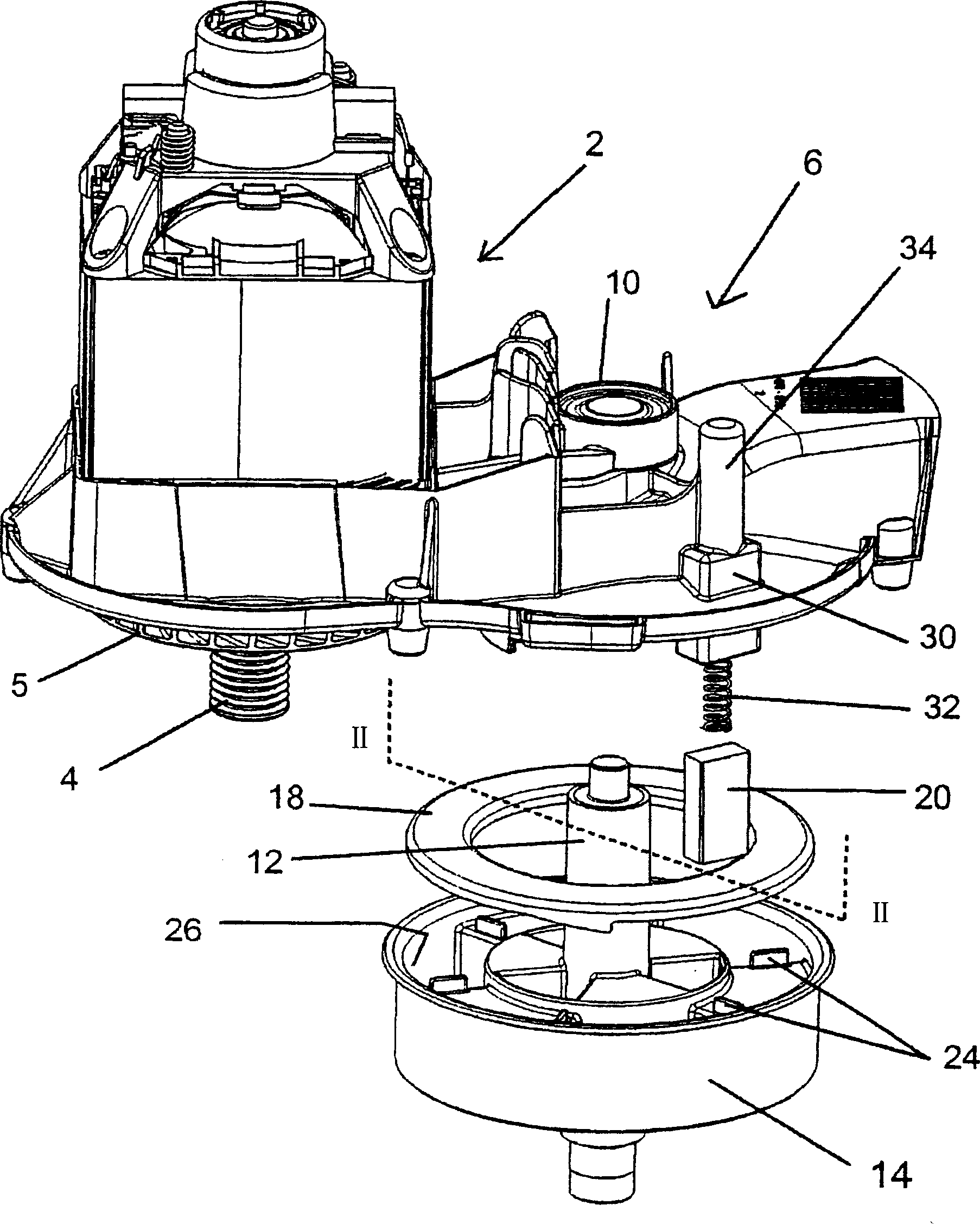
[0020] figure 1 The shown device comprises a motor housing 2 in which the motor is housed. A rotating drive shaft 4 protrudes from the motor through the motor housing 2 . A rotating fan or impeller 5 is mounted on the drive shaft 4 and is used to draw air through the motor 2 to cool the motor. The airflow is then directed to the braking components before being exhausted into the atmosphere.

[0021] A spindle mounting portion 6 is provided and connected or integrated with the motor housing 2 . The bearing 8 is provided in a bearing housing 10 on the spindle mounting portion 6 .

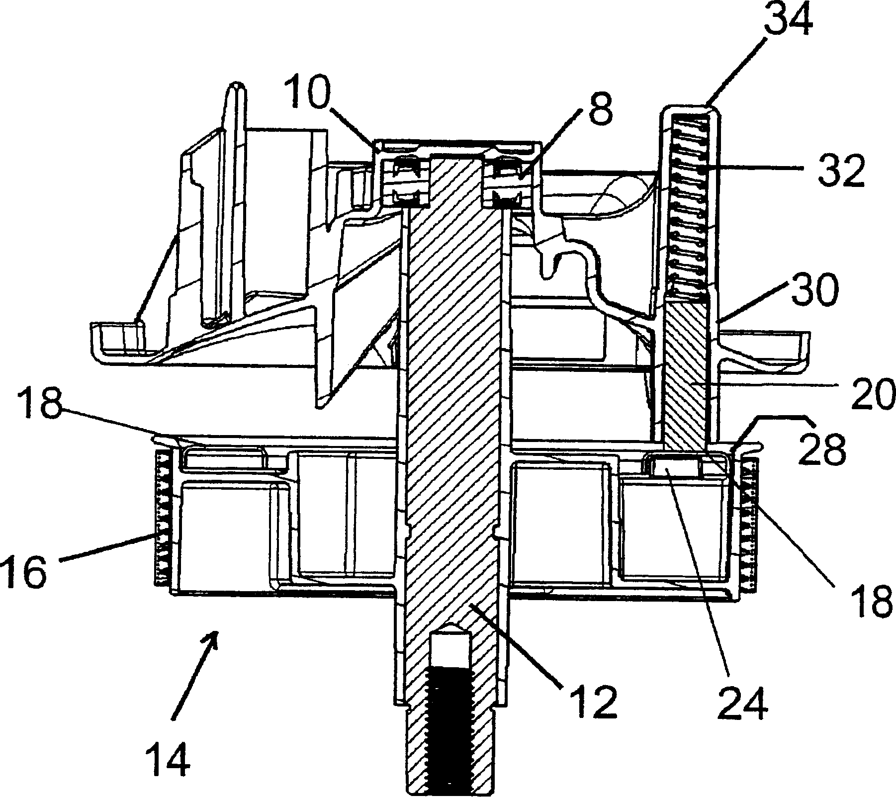
[0022] The spindle 12 is mounted for rotation on bearings 8 . A drum or pulley 14 is mounted on the spindle 12 in non-rotatable relationship. work as figure 2 As shown, the spindle 12 is mounted within the bearing 8 and the drum is held in position adjacent the drive shaft 4 such that a drive belt 16 can be fitted over the drive shaft 4 and the drum 14 to transmit the rotational drive from the ...


PUM


Abstract

The invention relates to improvements in or relating to braking systems, in particular to an apparatus for reducing the stopping time of a moving body in a gardening machine, for example, the rotary blade of a rotary lawnmower. The present invention also relates to a gardening machine having such an apparatus, more specifically to a lawncare machine such as lawnmowers. An apparatus for reducing the stopping time of a moveable body in a gardening machine is described, the apparatus comprises a brake acting permanently upon a component of the drive mechanism of the moveable body. In particular, an apparatus is described comprising an electric motor driving a driven shaft by means of an indirect drive assembly. The apparatus comprises a brake system in which a brake element is in substantially permanent contact with a component of the indirect drive assembly. In a preferred embodiment the brake system comprises an annular brake disc and the brake element comprises a brake pad biased into contact with the brake disc. The present invention also provides a lawncare apparatus comprising the apparatus described above, in particular, a lawnmower preferably of the rotary type.

Description

technical field [0001] The present invention relates to improvements in braking systems, and in particular to a device for shortening the stopping time of a moving body in garden machinery, such as the rotating blades of a rotary lawnmower. The invention also relates to a gardening machine comprising the above device, more particularly to a lawn care machine, such as a lawnmower. Background technique [0002] In garden machines with driven parts such as cutting blades, the driven parts continue to run for a period of time after the driving force (such as a motor) is removed. The time between turning off the motor and stopping the moving part is called the part's stop time and is very important. Some machinery has sharp and sharp parts that are easily accessible to the user, such as the blades on a lawn mower or the teeth on a scarifier, and for these potentially dangerous parts it is necessary to limit the stopping time for safety reasons. [0003] In known garden machine ...

Claims


Application Information

Patent Timeline
Patent Type & Authority Applications(China)
IPC IPC(8): A01D69/10A01G3/06A01D34/68F16D65/14
CPCA01D34/6812F16D2121/14F16D2127/001A01D2101/00
Inventor 安德鲁·奎格利阿德里安·库森
Owner ROBERT BOSCH GMBH
Why Eureka
Try Eureka