Three-D visual measuring quantity transmission method and plane target mark

A technology of three-dimensional vision and planar targets, which is applied in the direction of measuring devices, instruments, optical devices, etc.

Inactive Publication Date: 2007-02-14
BEIHANG UNIV
View PDF0 Cites 12 Cited by
  • Summary
  • Abstract
  • Description
  • Claims
  • Application Information

AI Technical Summary

Problems solved by technology

[0008] The object of the present invention is: aiming at the deficiencies of the existing methods, to propose a method and device for transmitting global measurement value of 3D vision field with simple operation, large measurement range, no cumulative error, and relatively low cost, so as to improve 3D vision. Measured magnitude transfer efficiency and accuracy

Method used


Image

  • Three-D visual measuring quantity transmission method and plane target mark
  • Three-D visual measuring quantity transmission method and plane target mark
  • Three-D visual measuring quantity transmission method and plane target mark

Examples


Embodiment

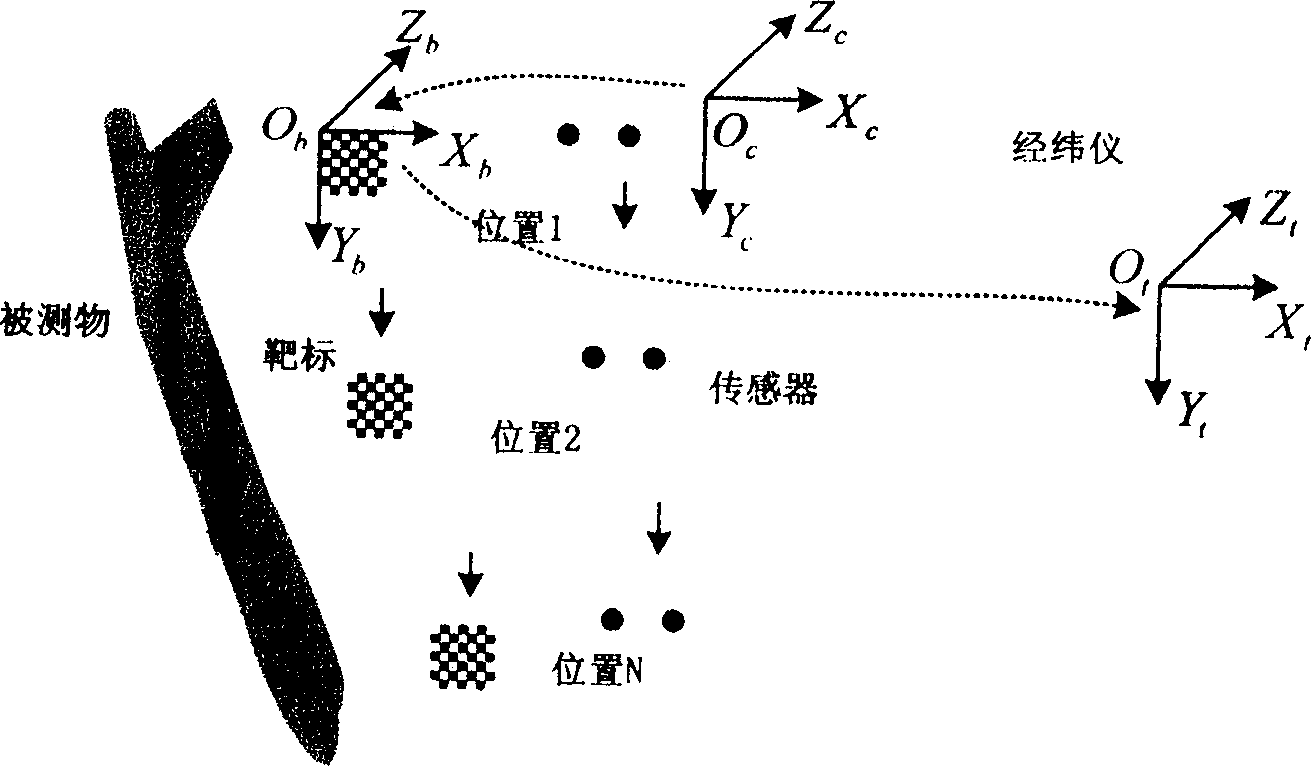
[0068] A planar object is measured at two positions using the present invention. The internal parameters of the camera are obtained as

[0069] Normalized focal length: fx=2008.169767

[0070] fy=2005.994692

[0071] Skew factor: Sx=-0.162852

[0072] Principal point coordinates: u0=400.782364

[0073] v0=289.420154

[0074]Radial distortion coefficient: k1=0.178490

[0075] k2=8.055620

[0076] The coordinate transformation matrix from the target to the camera at position 1 of the sensor is

[0077] T 1 cb = 0.995864 0.031416 0 . 085250 - 41.057332 0.030206 - ...


PUM


Abstract

A method for transmitting 3D visual measurement quantity includes moving visual transducer (VT) to certain position K, placing planar target to shoot target image and to pickup four non-colinear image character points, calculating out quantity transmission transform matrix ( QTTM) from target coordinate system (TCS) ObXbYbZb to video camera coordinate system (SCS ) OCXCYCZC, moving VT to position k+1 and using theodolite to aim four points on target then calculating out QTTM from TCS ObXbTbZb to theodolite CS OtXtYtZt , calculating QTTM from OCXCYCZC to OtXtYtZt of VT at position K and repeating above operation to unify all figures of VT under OtXtYtZt.

Description

technical field [0001] The invention belongs to three-dimensional vision measurement technology, and relates to the improvement of the transmission method of three-dimensional vision field global measurement value. Background technique [0002] Three-dimensional visual measurement technology is widely used in the shape measurement of automobiles, aircrafts, ships, and spacecraft, the measurement of large molds, the measurement of super-large components such as seamless steel pipes, the installation of large antennas, and deformation monitoring. A single vision sensor cannot complete the measurement of the entire large object through one measurement. In actual measurement, a flexible multi-vision detection system composed of multiple vision sensors is often used, or a single vision sensor is used to measure the flow around the large object. Therefore, the on-site global measurement value transfer of 3D vision measurement is the key, which determines the final measurement accu...

Claims


Application Information

Patent Timeline
IPC IPC(8): G01B11/00
Inventor 张广军魏振忠孙军华周富强
Owner BEIHANG UNIV
Why Eureka
Try Eureka