Doubling machine for metallic threads
A metal wire, metal wire technology, applied in textiles, papermaking, yarn and other directions, can solve the problems of low production efficiency, easy to break wires, and high production costs, and achieve high production efficiency, not easy to break wires, and good quality.
- Summary
- Abstract
- Description
- Claims
- Application Information
AI Technical Summary
Problems solved by technology
Method used
Image

Examples
Embodiment Construction
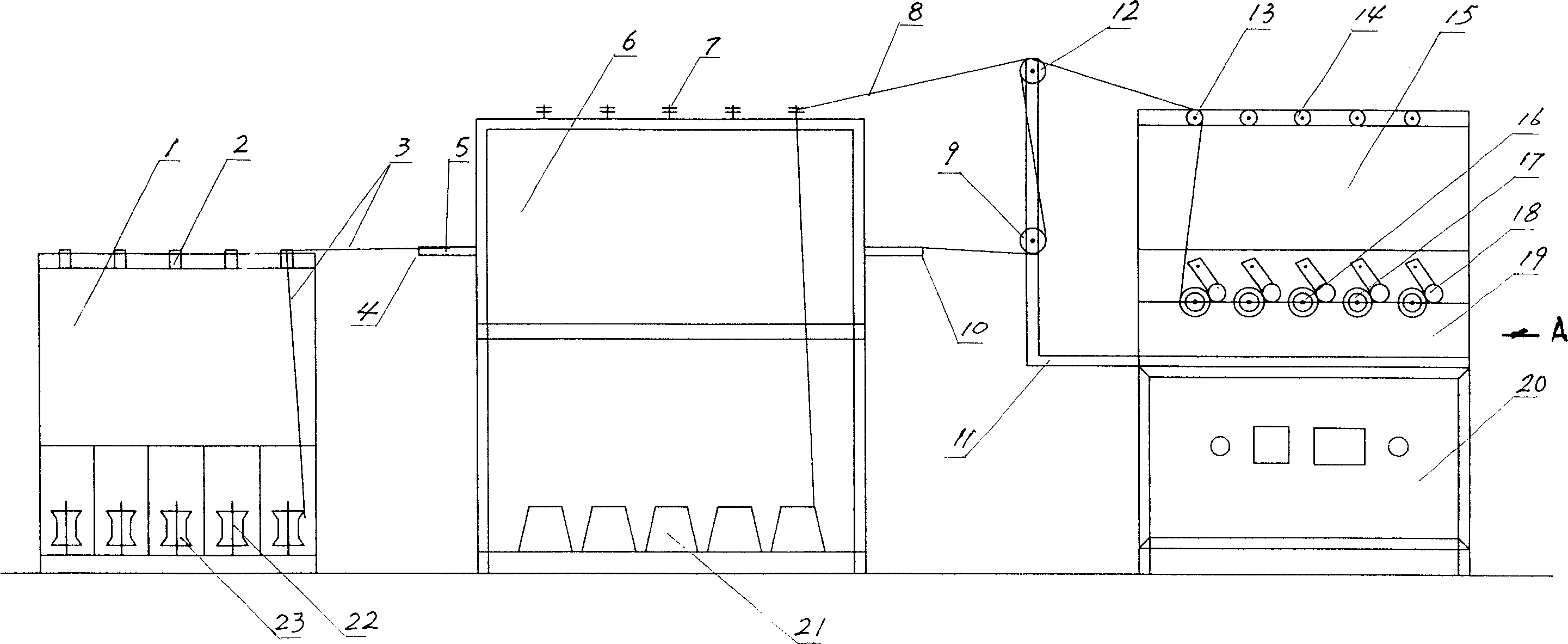
[0012] Such as figure 1 As shown, the metal wire doubling machine of the present invention includes a pay-off frame 1, an annealing furnace 6 and a wire take-up mechanism. Wherein the pay-off frame 1 is a frame structure, and its bottom is provided with five disc shafts 22 (the specific number depends on the need), and the five disc shafts are all vertically arranged, and their lower ends are welded on the bottom of the pay-off frame 1 On the crossbar, during work, a wire coil 23 that is wound with wire 3 is placed on each disk shaft 22 . Five ceramic rings 2 are arranged on the top of the pay-off frame 1 , corresponding to the disk shafts 22 below the five ceramic rings, and they are all welded on the cross bar at the top of the pay-off frame 1 .
[0013] Said annealing furnace 6 is a box-shaped structure, and its bottom is provided with five spindle shafts for placing yarn ingots 21 along both sides of its bottom. These spindle shafts are all vertically and equally spaced, ...
PUM
 Abstract
Description
Claims
Application Information