Working oil cooler

A technology of working oil and cooler, which is applied in the direction of fluid pressure actuators, soil movers/excavators, fluid pressure actuator system components, etc., which can solve the problems of high manufacturing cost and design restrictions, and achieve the increase of manufacturing cost , Avoid damage, prevent pulsation and abnormal high pressure

Active Publication Date: 2007-02-21
SHINTAKESHI IND
View PDF3 Cites 32 Cited by
  • Summary
  • Abstract
  • Description
  • Claims
  • Application Information

AI Technical Summary

Problems solved by technology

[0010] With such technology, while avoiding damage to the working oil cooler, abnormal high temperature of the working oil can be avoided. However, in addition to the usual hydraulic circuit, a new hydraulic pump with

Method used


Image

  • Working oil cooler
  • Working oil cooler
  • Working oil cooler

Examples


Embodiment Construction

[0026] Hereinafter, the best mode for carrying out the present invention will be described with reference to the drawings.

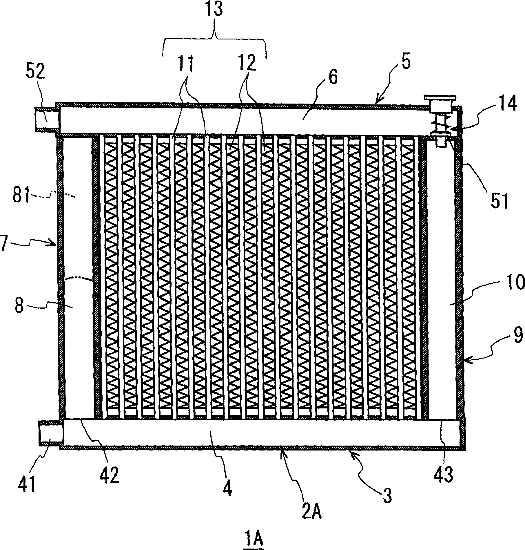
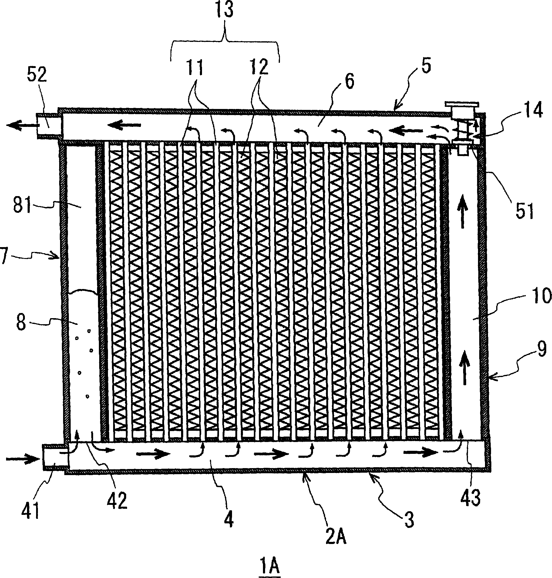
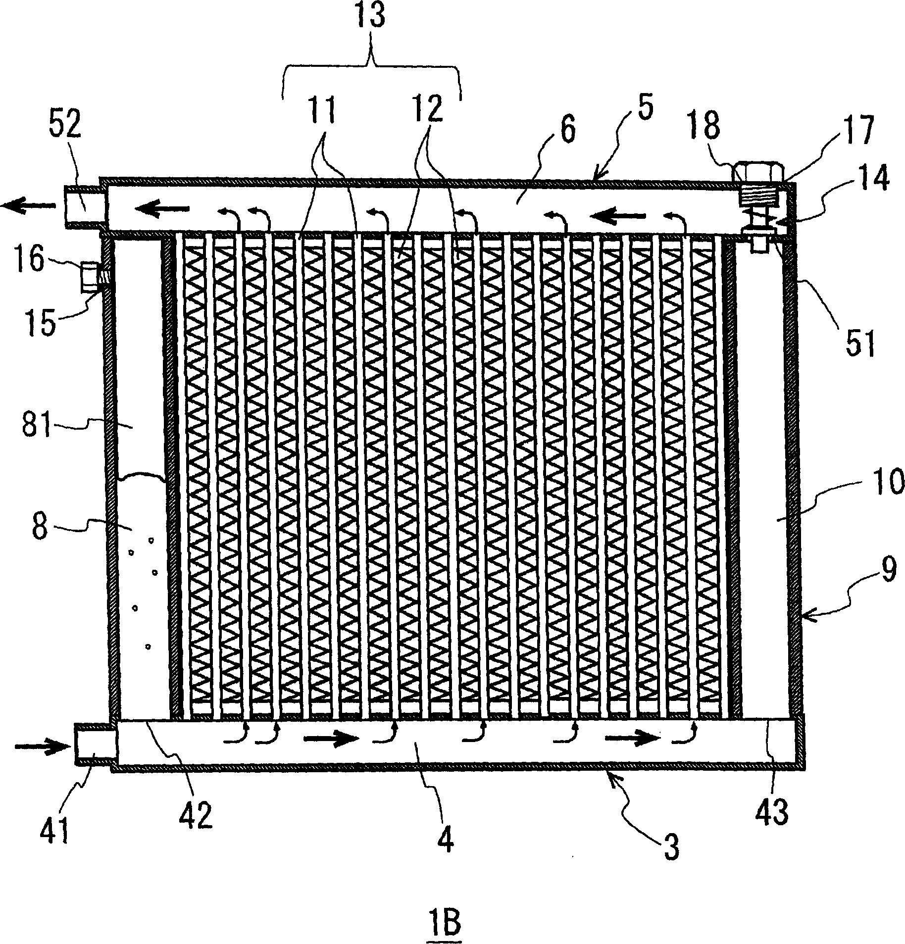
[0027] figure 1 It is an example of an embodiment of the present invention, and is a longitudinal sectional view seen from the front side of hydraulic oil cooler 1A. The hydraulic oil cooler 1A is formed as a solid frame body 2A made of roughly square cast aluminum or the like as a whole, and a horizontally long rectangular inlet chamber 4 and a horizontally long outlet chamber 6 arranged in parallel therewith are respectively arranged in the opposing horizontal frame 3, 5, between these inlet chambers 4 and outlet chambers 6 is connected a heat radiation section 11 that is formed by arranging a plurality of pipes in parallel, and a heat exchange section 13 is arranged between the heat dissipation sections 11, and the heat exchange section 13 is equipped with The heat dissipation member 12 formed by bending a thin metal plate can also be provided with ...


PUM


Abstract

A cooler of working oil is prepared as forming said cooler by connecting multiple heat conduction tubes in parallel way to form heat radiation unit, setting formed cooler between inlet chamber at lead in port of working oil sent from oil pressure device and outlet chamber at send out port of working oil sent from oil pressure device, connecting buffer chamber with air storage unit through to inlet chamber for utilizing air in air storage unit to absorb pulsation and pressure rise of working oil at inlet chamber in order to cool working oil stably.

Description

technical field [0001] The present invention relates to a working oil cooler which is connected to a hydraulic circuit for controlling hydraulic equipment and cools working oil whose temperature increases with use of the hydraulic equipment. Background technique [0002] For example, hydraulic forklifts, hydraulic stamping machines, etc., hydraulic equipment that has a hydraulic circuit and uses a hydraulic motor to send working oil to make the actuator work, when using high-pressure working oil and high-resistance actuators etc., the temperature of the working oil tends to increase, and as a result, there are problems such as deterioration of the working oil and leakage from the sliding part due to a drop in viscosity. The pipe body or sealing member constituting the hydraulic circuit may also be damaged due to an abnormal temperature rise of the working oil. [0003] Therefore, if Figure 4 As shown, in the hydraulic circuit from the working oil tank 20 through the hydrau...

Claims


Application Information

Patent Timeline
IPC IPC(8): F15B21/04E02F9/22
Inventor 十万干雄
Owner SHINTAKESHI IND
Why Eureka
Try Eureka