

Loosening able plug in type joint in use for inserting to tubular insertion piece with peripheric capped edge
A technology of plug-in joints and inserts, used in mechanical equipment, couplings, etc., to solve problems such as danger and inadvertently compressing elastic rings together during installation
- Summary
- Abstract
- Description
- Claims
- Application Information
AI Technical Summary
Problems solved by technology
Method used
Image

Examples
Embodiment Construction
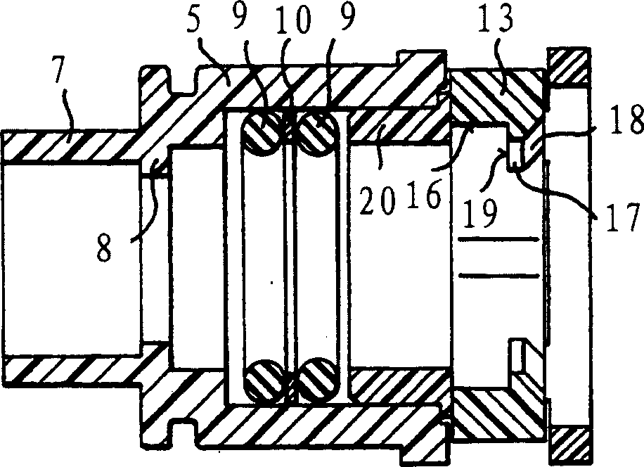
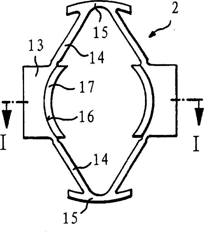
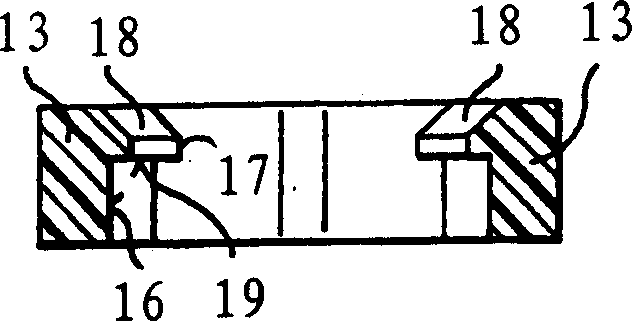
[0019] The plug-in joint shown in the figures comprises a receiving shell 1 and a locking ring or locking element 2 made of a hard elastic plastic material. The plug-in connector is designed to receive a tubular insert 3 with a peripheral rib 4, which may be the end of a catheter made of rigid material, or may be connected to a softer tube by conventional means. Ends formed by intermediate pieces in pipes made of material.
[0020] according to Figure 4 , The cylindrical shell wall 5 of the receiving shell 1 forms an inner receiving cavity 6 with several steps inside for accommodating the insert 3 . At the distal end of the receiving chamber 6, the receiving housing has a stop ring or stop ring and a cylindrical concentric connecting stub 7 for connecting the connector to a fluid connection line (not shown in the figure). The receiving cavity 6 starts from the opposite side of the inlet end and is an inner cavity 6', the inner diameter of the inner cavity corresponds to the...
PUM
 Abstract
Description
Claims
Application Information