Method, system and equipment for transferring result of measuring total received power in broadband

A technology of total received power and measurement results, applied in the field of general public wireless interfaces, which can solve the problems of limited software processing capability, inability to transmit measurement results in time, and inability to meet actual business needs, and achieve good compatibility.

Active Publication Date: 2007-02-21
HUAWEI TECH CO LTD
View PDF0 Cites 8 Cited by
  • Summary
  • Abstract
  • Description
  • Claims
  • Application Information

AI Technical Summary

Problems solved by technology

[0009] In practical application, the above scheme has the following problems: the existing RTWP measurement result reporting method is not suitable for some existing enhanced services
[0010] The main reason for this situation is that in some enhanced services, due to the requirements of the baseband algorithm on the REC, the RE needs to measure the RTWP every 2ms a

Method used


Image

  • Method, system and equipment for transferring result of measuring total received power in broadband
  • Method, system and equipment for transferring result of measuring total received power in broadband

Examples


Embodiment Construction

[0039] In order to make the object, technical solution and advantages of the present invention clearer, the present invention will be further described in detail below in conjunction with the accompanying drawings.

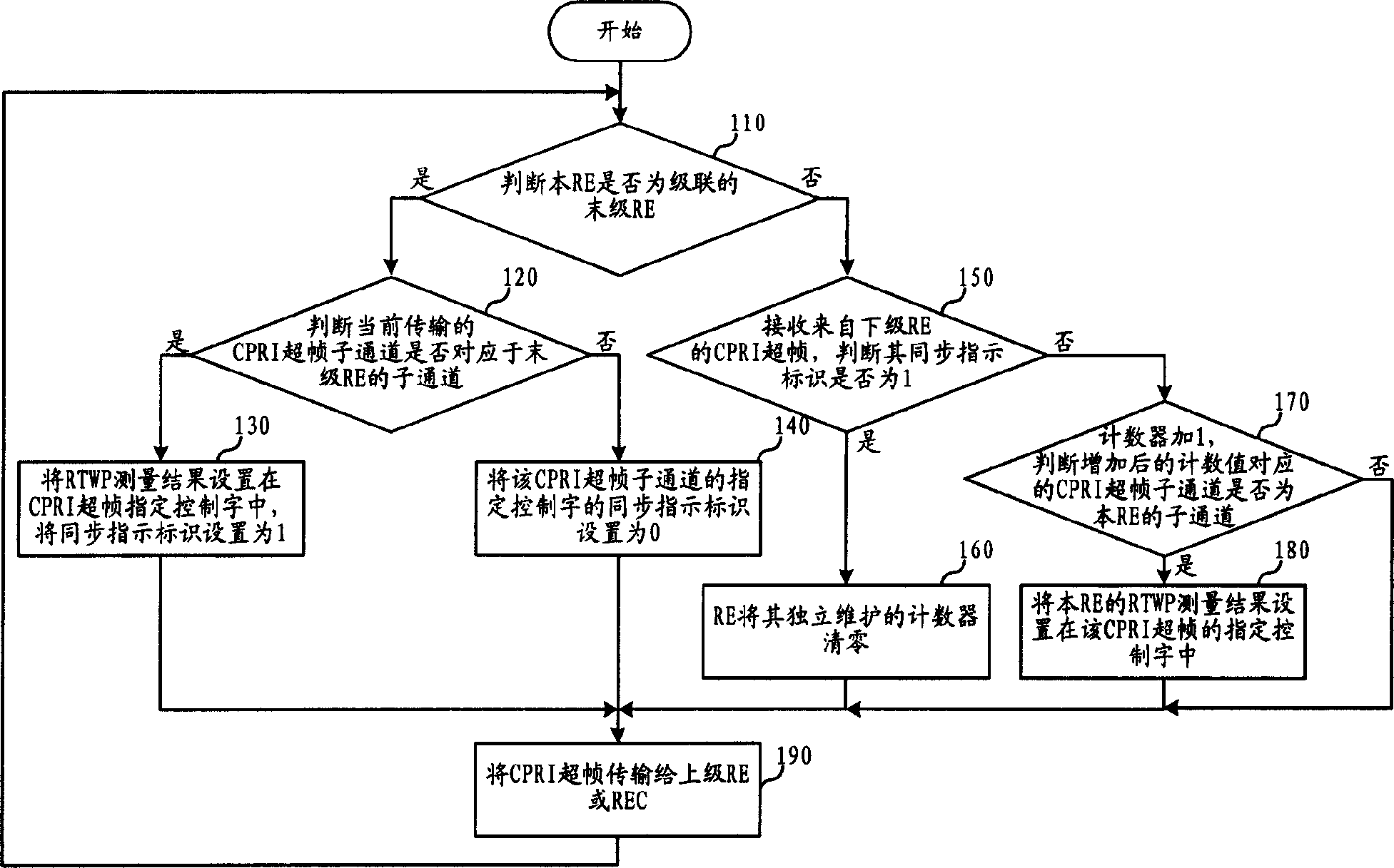
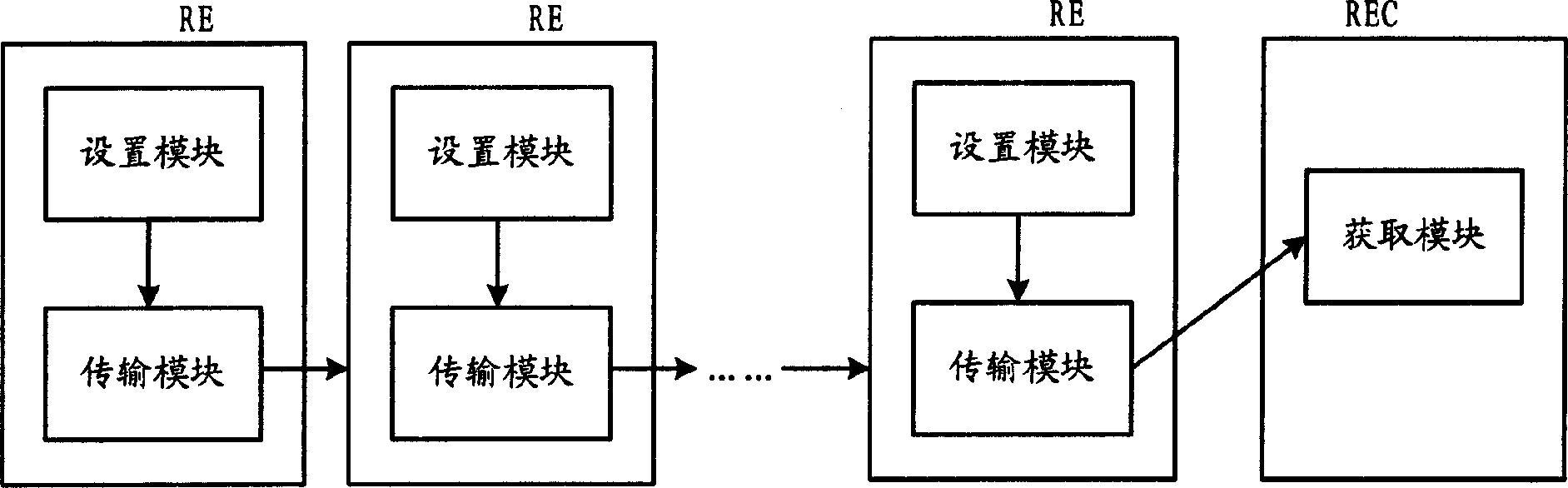
[0040] The core of the present invention is that the RE directly implements the transmission of the RTWP measurement result at the CPRI interface layer 1 by setting the RTWP measurement result in the control word in the manufacturer-defined area of ​​the CPRI superframe, thereby shortening the transmission cycle of the RTWP measurement result, Meet the requirements of most enhanced services; after the REC receives the CPRI superframe, it can obtain the RTWP measurement result of the RE from the corresponding control word.

[0041] The first embodiment of the present invention will be described below based on the principles of the present invention.

[0042] In this embodiment, the RE transmits its RTWP measurement results through the control word specified in the ...


PUM


Abstract

The invention is used to let RE capable of transmitting RTWP measuring result in a shorter cycle through CPRI interface. Wherein, RE sets the RTWP measuring result in a control word appointed by a CPRI superframe, and transmits it to REC through CPRI interface layer 1; REC gets the RTWP measuring result from the appointed control word. Because the CPRI superframe is directly transmitted from the CPRI interface layer 1, so the RTWP measuring result can be transmitted in very shorter cycle; multi REs can share same control word in CPRI superframe with TDM method to transmit RTWP measuring result such that the control word resource can be sufficiently utilized.

Description

technical field [0001] The present invention relates to the field of communications, and in particular to Common Public Radio Interface (Common Public Radio Interface, "CPRI" for short) technology. Background technique [0002] In various communication systems, cascade networking is a very common networking method. In a cascaded network, a master node (MN for short) and multiple slave nodes (Slave Node, SN for short) may be included. Generally, in a cascaded network, each node will contain at least one sending port and at least one receiving port, and adjacent nodes are connected through links between ports. Generally, the direction from the master node to the slave node is defined as the downlink direction, and the direction from the node to the slave node is generally defined as the downlink direction. The direction of the master node is the uplink direction. In a cascaded network, the master node is also called the root node, the last slave node in the downlink directio...

Claims


Application Information

Patent Timeline
IPC IPC(8): H04B7/005H04B17/00H04B7/26H04Q7/38H04B17/327
Inventor 李刚
Owner HUAWEI TECH CO LTD
Why Eureka
Try Eureka