Forcipated mutual-inductor, forcipated ammeter and verification method of forcipated ammeter

A technology of clamp transformers and clamp ammeters, which is applied in the direction of measuring current/voltage, instruments, and measuring electrical variables, etc., and can solve problems such as power outages, loss of factories, institutions, and casualties

Active Publication Date: 2007-02-28
ZHUHAI KEHUI ELECTRICAL APPLIANCE CO LTD
View PDF3 Cites 20 Cited by
  • Summary
  • Abstract
  • Description
  • Claims
  • Application Information

AI Technical Summary

Problems solved by technology

However, if this traditional current measurement method is used in high-voltage occasions (such as measuring the current in high-voltage wires, etc.), there are at least two disadvantages below: first, the power supply of the circuit to be tested must be cut off first, Connecting the current measuring instrument and then turning on the power supply is not only a cumbersome process, but also needs to cut off the power, which will cause great trouble to the public power grid, because frequent power outages not only bring troubles to residents' electricity consumption, but also bring troubles to factories and institutions. Second, when using this method to measure the current in high-voltage wires, the risk factor is relatively large, especi...

Method used


Image

  • Forcipated mutual-inductor, forcipated ammeter and verification method of forcipated ammeter
  • Forcipated mutual-inductor, forcipated ammeter and verification method of forcipated ammeter
  • Forcipated mutual-inductor, forcipated ammeter and verification method of forcipated ammeter

Examples


Embodiment Construction

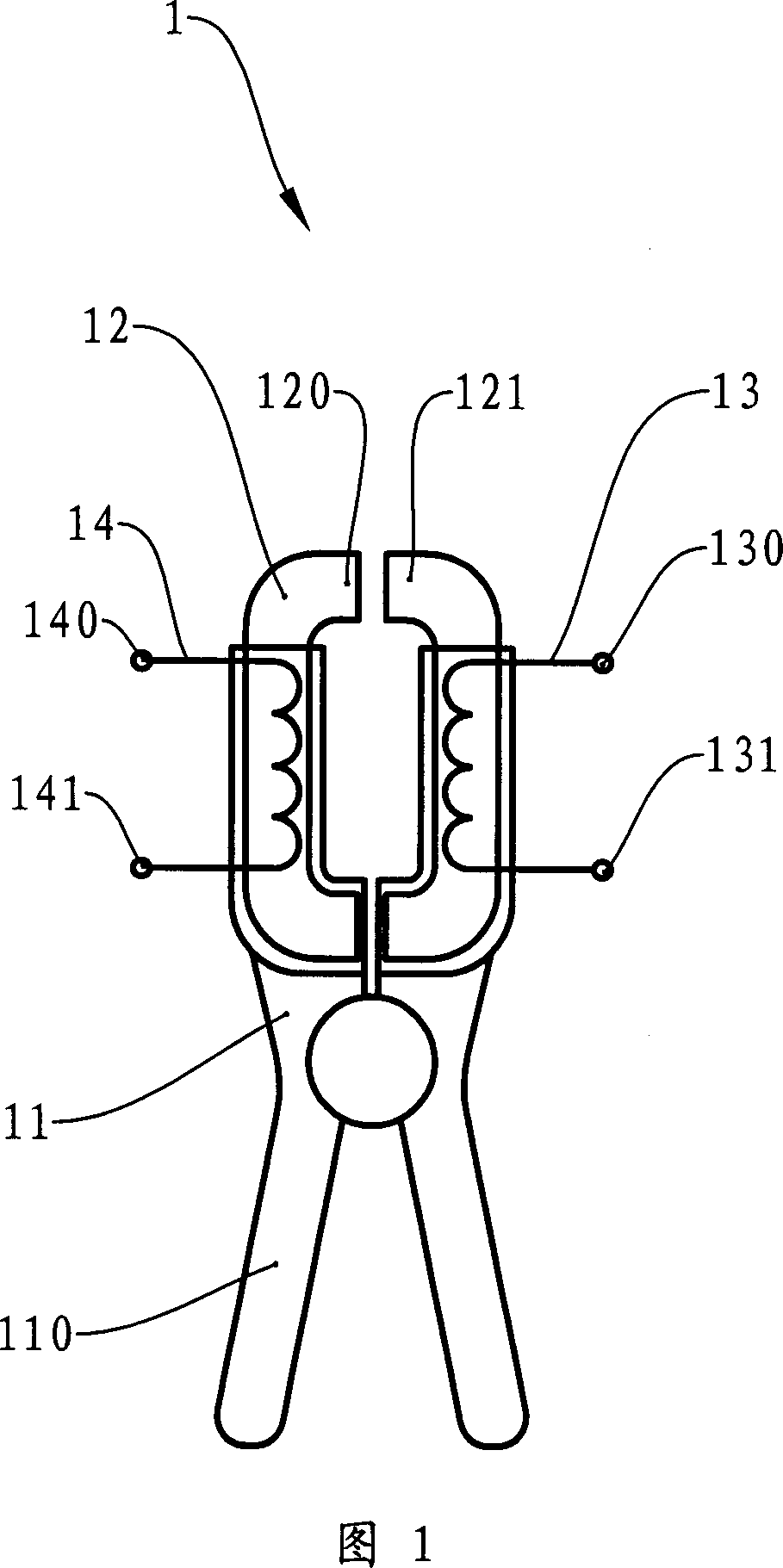
[0018] Referring to FIG. 1 , the clamp transformer 1 of the present invention includes a housing 11 , an iron core 12 housed in the housing 11 , a detection coil 13 and a correction coil 14 arranged on the iron core 12 .

[0019] The casing 11 has an "X" shaped handle 110 , and the iron core 12 is divided into a left half 120 and a right half 121 , and operating the handle 110 can separate or close the left half 120 and the right half 121 . When the left half body 120 and the right half body 121 are closed, a complete magnetic circuit is formed in the iron core 12 .

[0020] The detection coil 13 has two connections 130 , 131 and the correction coil 14 has two connections 140 , 141 .

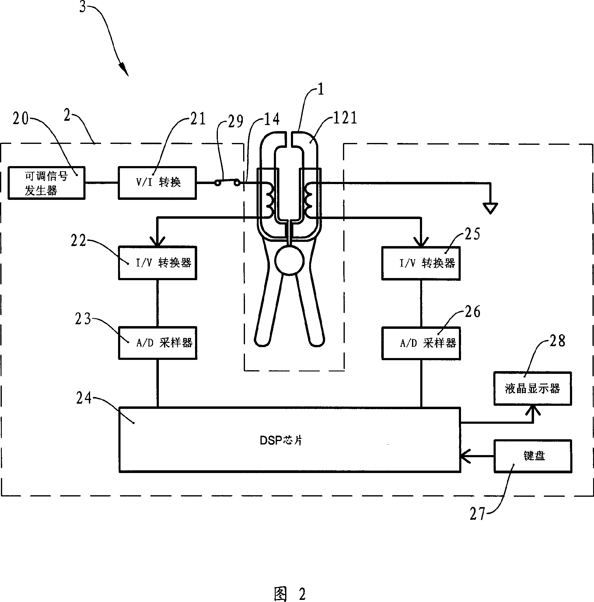
[0021] FIG. 2 is a schematic structural diagram of the clamp ammeter 3 according to the present invention. The clamp ammeter 3 is composed of a clamp transformer 1 and an auxiliary circuit 2 . All circuits within the dotted line box in FIG. 2 can be regarded as auxiliary circuits 2 . The role...


PUM


Abstract

The invention relates to a split-core transformer and a split-core current meter, and relative self correct method of split-core current meter, wherein said split-core transformer comprises frame, iron core, detecting coil on the iron core, and correcting coil induced with detecting coil; the iron core can be separated into two semi bodies; said frame also comprises a device for controlling the combination and separation of two semi bodies; the split-core current meter has said split-core transformer and relative auxiliary circuit. Since it uses correcting coil, the split-core transformer and split-core current meter can pre-correct the error before detection.

Description

technical field [0001] The invention relates to a device for measuring current or voltage, in particular to a clamp ammeter for measuring current. Background technique [0002] Generally, traditional current measuring instruments such as ammeters and multimeters are used to measure the current. After connecting such current measuring instruments in series to the circuit, the current magnitude of the corresponding branch can be directly obtained. However, if this traditional current measurement method is used in high-voltage occasions (such as measuring the current in high-voltage wires, etc.), there are at least two disadvantages below: first, the power supply of the circuit to be tested must be cut off first, Connecting the current measuring instrument and then turning on the power supply is not only a cumbersome process, but also needs to cut off the power, which will cause great trouble to the public power grid, because frequent power outages not only bring troubles to re...

Claims


Application Information

Patent Timeline
IPC IPC(8): G01R15/00G01R19/00G01R35/00
Inventor 王银章肖增林张翔向长清王峰
Owner ZHUHAI KEHUI ELECTRICAL APPLIANCE CO LTD
Why Eureka
Try Eureka