Two-rolling bearing type pumping rod centralizer

A technology of rolling bearings and centralizers, which is applied to drill pipes, drilling equipment, earthwork drilling, etc., and can solve the problems of poor wear resistance and low fatigue life

Inactive Publication Date: 2007-03-07
北京百世卓越科技发展有限公司 +2
View PDF0 Cites 5 Cited by
  • Summary
  • Abstract
  • Description
  • Claims
  • Application Information

AI Technical Summary

Problems solved by technology

[0003] The purpose of the present invention is to develop a double rolling bearing type sucker rod centralizer to overcom...

Method used


Image

  • Two-rolling bearing type pumping rod centralizer
  • Two-rolling bearing type pumping rod centralizer

Examples


Embodiment Construction

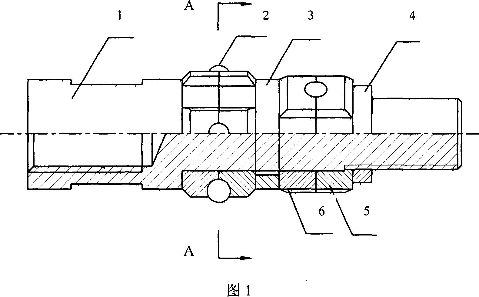
[0007] The embodiment of the present invention is described in detail below in conjunction with accompanying drawing: two righting covers adopt segmented structure, are made up of righting cover sub-block 1 (5) and righting cover sub-block 2 (6). The rolling balls (2) are positioned in the holes formed by the docking of the centralizing sleeve sub-blocks 1 (5) and 2 (6), and are arranged in a regular polygon. Two centralizing sleeves composed of blocks (5) and (6) and a limit ring (3) are fixed on the centralizer rod body (1) through the fastening ring (4). The two centralizing sleeves are arranged staggeredly along the axis of the centralizer rod (1), if the rolling balls are arranged in a regular quadrilateral (or pentagon, hexagonal) shape, the angle between the two centralizing sleeves and the rolling balls (2) is 45°( or 36°, 30°). The centralizer rod body (1) is connected with the sucker rods at both ends through threads. During the working process, the crude oil rises...


PUM


Abstract

This invention relates to double rolling bear oil extraction bar correction device, which comprises corrector bar with screw on ends, composite correction cover, rolling bar, limit ring and fix ring. The invention is characterized by the following: setting two correction cover with each one composed of two correction blocks and four or six hard nanometer ceramics rolling sphere part as hole tank of protruding part with anti-ware and anti-erosion property; the rolling sphere part is in order of four or six edges.

Description

technical field [0001] The invention relates to an oil well sucker rod connection centralizer, in particular to a double rolling bearing type sucker rod centralizer with good friction resistance and corrosion resistance. Background technique [0002] Rod pumping units are mostly used in present oil fields. It is driven by the pumping unit through the sucker rod string to lift the crude oil to the wellhead. When the distribution of the oil layer is deep from the ground, the sucker rod string is very long or the oil well itself is inclined or bent, and there is a corrosive medium in the working environment of the sucker rod, which leads to serious wear and corrosion of the sucker rod and tubing. The existing sucker rod centralizer has poor wear resistance and corrosion resistance, and has a low fatigue life, resulting in frequent accidents of sucker rod fracture or oil pipe being worn through. Contents of the invention [0003] The purpose of the present invention is to de...

Claims


Application Information

Patent Timeline
IPC IPC(8): E21B17/10
Inventor 任君合唐委校张本利
Owner 北京百世卓越科技发展有限公司
Why Eureka
Try Eureka