System for the distributed measurement of structural bending

A distributed and decentralized technology, applied in the direction of machine/structural component testing, measuring devices, elastic testing, etc., can solve problems such as impractical and expensive

Inactive Publication Date: 2007-03-14
COMMISSARIAT A LENERGIE ATOMIQUE ET AUX ENERGIES ALTERNATIVES
View PDF1 Cites 18 Cited by
  • Summary
  • Abstract
  • Description
  • Claims
  • Application Information

AI Technical Summary

Problems solved by technology

Such fluctuations can be caused by connection problems, aging of adhesive connections, slight bends along the measuring fiber, etc.
In addition, since the sensors must be calibrated individually and the set point can change over time (for the same reasons as above), the sensors must be recalibrated periodically, which is expensive and often impractical in the field, especially if the structure is being built underground. sealed case

Method used


Image

  • System for the distributed measurement of structural bending
  • System for the distributed measurement of structural bending
  • System for the distributed measurement of structural bending

Examples


Embodiment

[0038] Metrology characteristics of Bregg grating

[0039] The wavelength of the Bragg grating varies directly with the temperature T and the deformation ε along the fiber axis.

[0040] The relative change of the Bragg wavelength of the Bragg grating (free grating, without bonding) is a function of temperature, which can be written as:

[0041] Δλ B λ B = aΔT = ( α + ξ ) ΔT ≈ 7 · 10 - 6 · ΔT - - - ( 1 )

[0042] At a wavelength of 1.55μm, this coefficient has the order of 10-12pm / K according to different optical fibers. When the Bragg grating is bonded to...


PUM


Abstract

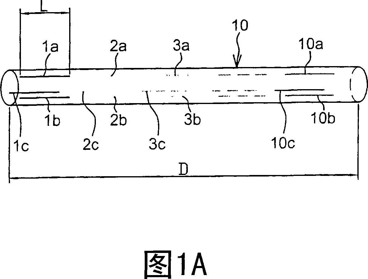
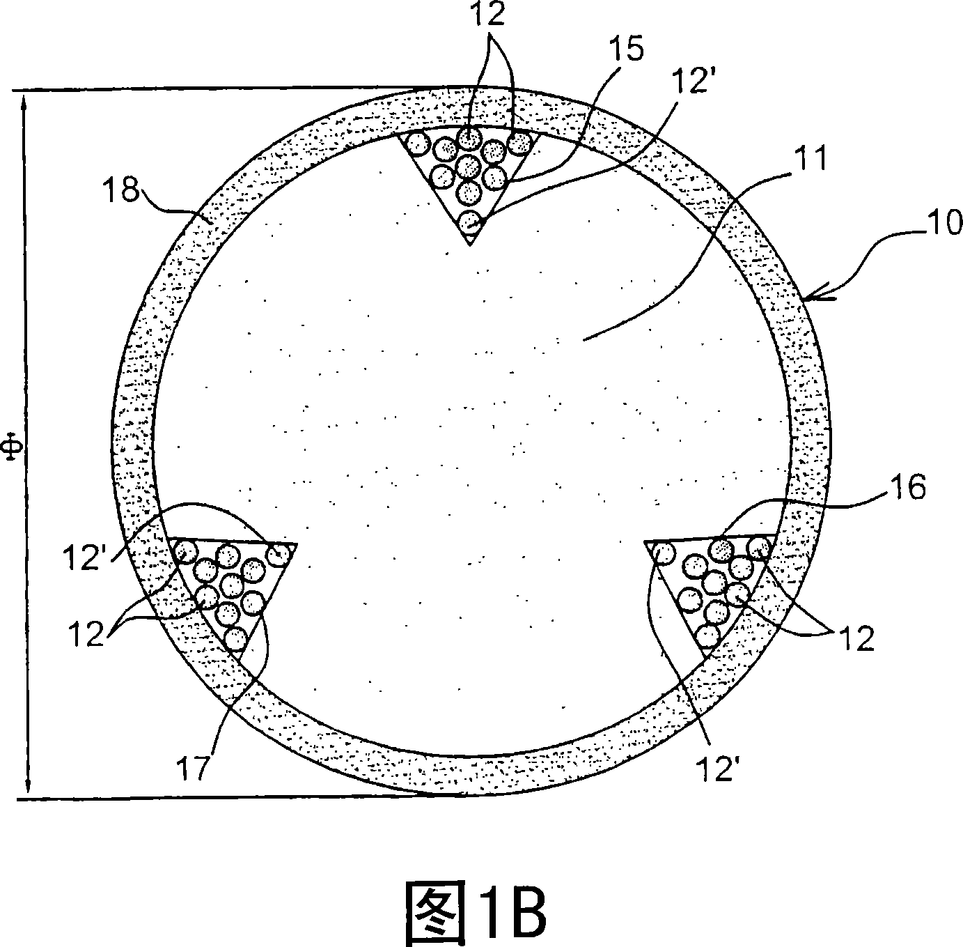
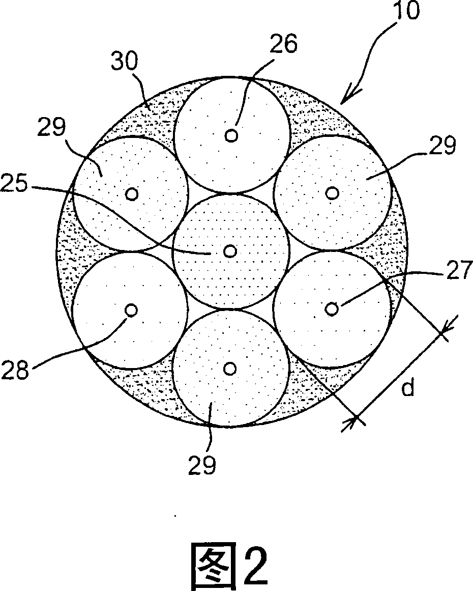
The invention relates to a system for the distributed measurement of structural bending and axial deformations, comprising: at least one instrumented filiform device (10) which is used for the distributed measurement of axial deformations and bending, and means for processing the measurement signals delivered by said device. According to the invention, each device comprises a cylindrical frame (11) which supports at least three optical fibres (12) along the periphery thereof, said fibres being disposed locally parallel to the axis of the frame. Moreover, the aforementioned processing means make use of means for the spectral or temporal multiplexing of the signals originating from the optical fibres.

Description

Technical field [0001] The present invention relates to a distributed measurement system for bending of a structure, which includes a linear cable-shaped device equipped for such measurement and a device for processing the measurement signal generated by the above-mentioned device. Background technique [0002] In the field of civil engineering construction (buildings, bridges, roads, railroad tracks, etc.), uneven settlement and even unforeseen collapse (partial collapse) can cause serious ground and underground accidents and lead to extremely high maintenance costs. Such incidents may be due to the existence of natural or man-made cavities (mines, tunnels, etc.) that have not been marked, or even if known, are not strong enough and overloaded. [0003] Public construction engineering companies need to have a measurement system suitable for existing structures (or structures under construction) that can monitor accurate changes in ground subsidence (spatially along the horizonta...

Claims


Application Information

Patent Timeline
Patent Type & Authority Applications(China)
IPC IPC(8): G02B6/44G01D5/353G01M5/00G01M11/08G02B6/02
CPCG01D5/35354G01D5/35303G01M5/0041G01D5/35364G01M5/0025G02B6/022G01D5/35316G01M5/0091G01M11/085G01D5/353
Inventor 西尔万·马涅皮埃尔·费迪南
Owner COMMISSARIAT A LENERGIE ATOMIQUE ET AUX ENERGIES ALTERNATIVES
Why Eureka
Try Eureka