Code-division multiplex signal decorrelation/identification method

一种码分多址、区分系统的技术,应用在传输系统、复用码分配、电气元件等方向,能够解决站间干扰阻碍、可容纳的用户数量低频率利用效率、不容易获得精确的导频响应等问题

Inactive Publication Date: 2007-03-14
UNIV OF TSUKUBA
View PDF0 Cites 7 Cited by
  • Summary
  • Abstract
  • Description
  • Claims
  • Application Information

AI Technical Summary

Problems solved by technology

However, since communications from a large number of stations share the same time slot and the same frequency band, there is a problem that an increase in the number of users to be accumulated per unit frequency band is hindered by inter-station interference (noise)
More specifically, there is a problem that the number of users that can be accommodated is limited resulting in a system with low frequency utilization efficiency
More specifically, since 1 bit of data / symbol is transmitted by using one symbol slot and a bandwidth in which 2 bits / symbol can be transmitted by QPSK (Quadrature Phase Shift Keying), the pilot consumes the same amount of time as the data. sizable resource that consumes equal resources
In addition, due to the characteristics of multiple channels, the pilots experience interference from both data symbols from the same user and pilot / data symbols from other users, so there is also the problem that it is not easy to obtain an accurate pilot response

Method used


Image

  • Code-division multiplex signal decorrelation/identification method
  • Code-division multiplex signal decorrelation/identification method
  • Code-division multiplex signal decorrelation/identification method

Examples


Embodiment Construction

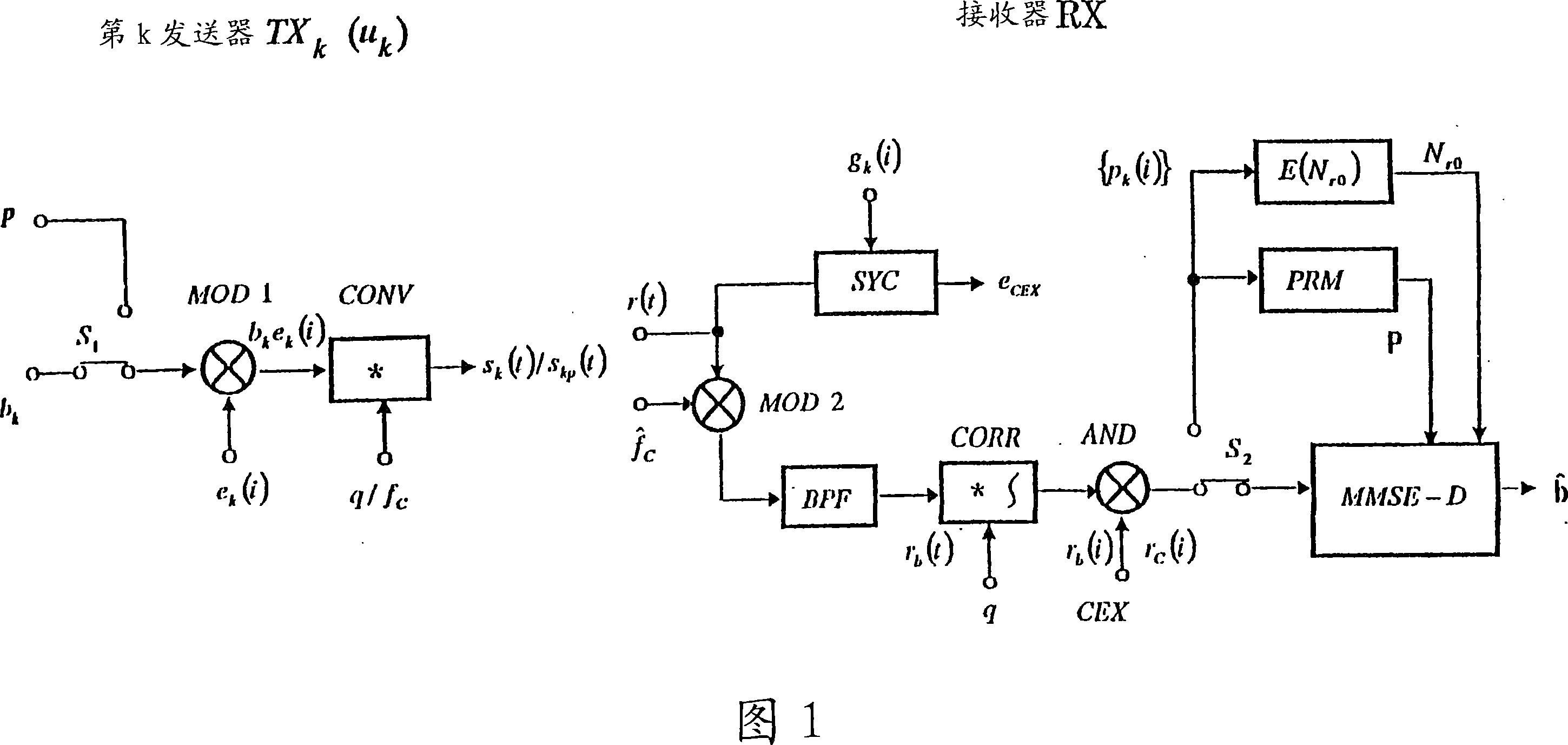
[0055] FIG. 1 is an explanatory diagram of assistance in the first embodiment of the present invention, and is a block diagram showing the structure of a transceiver of a code division multiple access (CDMA) communication system. In Figure 1, the left side shows the kth user u k The kth (k=0, 1, 2, ... K) transmitter TX used k , the right shows the receiver RX used in the base station. Use symbol period as T E the binary data b k (∈±1) as pair to transmitter TX k input of. Symbol p represents a pilot input set by p=1. Use switch S shown in figure (a) 1 The pilot input p is transmitted in a time-division manner at such a timing that it does not overlap in time with transmission data of all users and pilots transmitted by other users. Enter b at modulator MOD k Using protection (to be described later) on the envelope sequence e k (i) Modulate to generate E pulse sequence b k e k (i). The convolution multiplier CONV uses the corresponding pulse pairs of the above pul...


PUM


Abstract

The present invention relates to a decorrelation distinguishing system of code division multiple access signals, and provides a new multi-user receiver configuration technology, which solves the problem of multi-user receivers such as interference canceller, decorrelator and minimum mean square error detection of user signals Problems with separating functions. That is, a decorrelation / identification method of a code division multiple access signal is provided to realize the power band amplitude product required for 1-bit transmission (which is an evaluation benchmark for the CDMA method much better than the performance of the above-mentioned method And add a function of sequentially judging the best user to the conventional minimum mean square error detector MMSE-D represented by the dotted line in the block diagram of the sequential detection type minimum mean square error detection method.

Description

technical field [0001] The present invention relates to a code division multiple access communication system (CDMA) using spread spectrum modulation, which can reduce white noise mixed in transmission processing and interference noise generated in multi-user signal separation processing by a receiver, and can enhance frequency Utilization efficiency, and can reduce the power bandwidth product. In this case, a modulation / demodulation technique for a transceiver of a mobile communication system in which spread spectrum modulation is applied to a BPSK signal is taken as an example to explain a user separation technique for a multi-user receiver. Background technique [0002] Spread spectrum communication is a system using a spread spectrum modulation technique in which a spread sequence is modulated by transmitting data. Due to this spread modulation, a data sequence having a relatively narrow bandwidth is spectrally spread into a wide frequency band, generating a spread spect...

Claims


Application Information

Patent Timeline
Patent Type & Authority Applications(China)
IPC IPC(8): H04B1/707H04B1/7103H04J13/22
CPCH04B1/71055H04B1/71072
Inventor 畔柳功芳末广直树大竹孝平松藤信哉小沢智富田光博
Owner UNIV OF TSUKUBA
Why Eureka
Try Eureka