
Breath holding MR imaging method, MRI apparatus, and tomographic imaging apparatus

An imaging method and tomography technology, applied in breath-hold MR imaging, MRI device, and breath-hold tomography imaging, can solve problems such as changes in the position of organs

Inactive Publication Date: 2007-03-21
GE MEDICAL SYST GLOBAL TECH CO LLC
View PDF2 Cites 9 Cited by
  • Summary
  • Abstract
  • Description
  • Claims
  • Application Information

AI Technical Summary

Problems solved by technology

However, when there are two or more repeated breath-hold imaging sessions with expiratory intervals in between, fluctuations in breath-hold timing within each interval will continue and eventually the position of the diaphragm will change when the breath is actually held
This also poses a problem for Patent Document 2 in that the position of the organ relative to the slice position changes during each breath-hold imaging

Method used


Image

  • Breath holding MR imaging method, MRI apparatus, and tomographic imaging apparatus
  • Breath holding MR imaging method, MRI apparatus, and tomographic imaging apparatus
  • Breath holding MR imaging method, MRI apparatus, and tomographic imaging apparatus

Examples


no. 1 approach

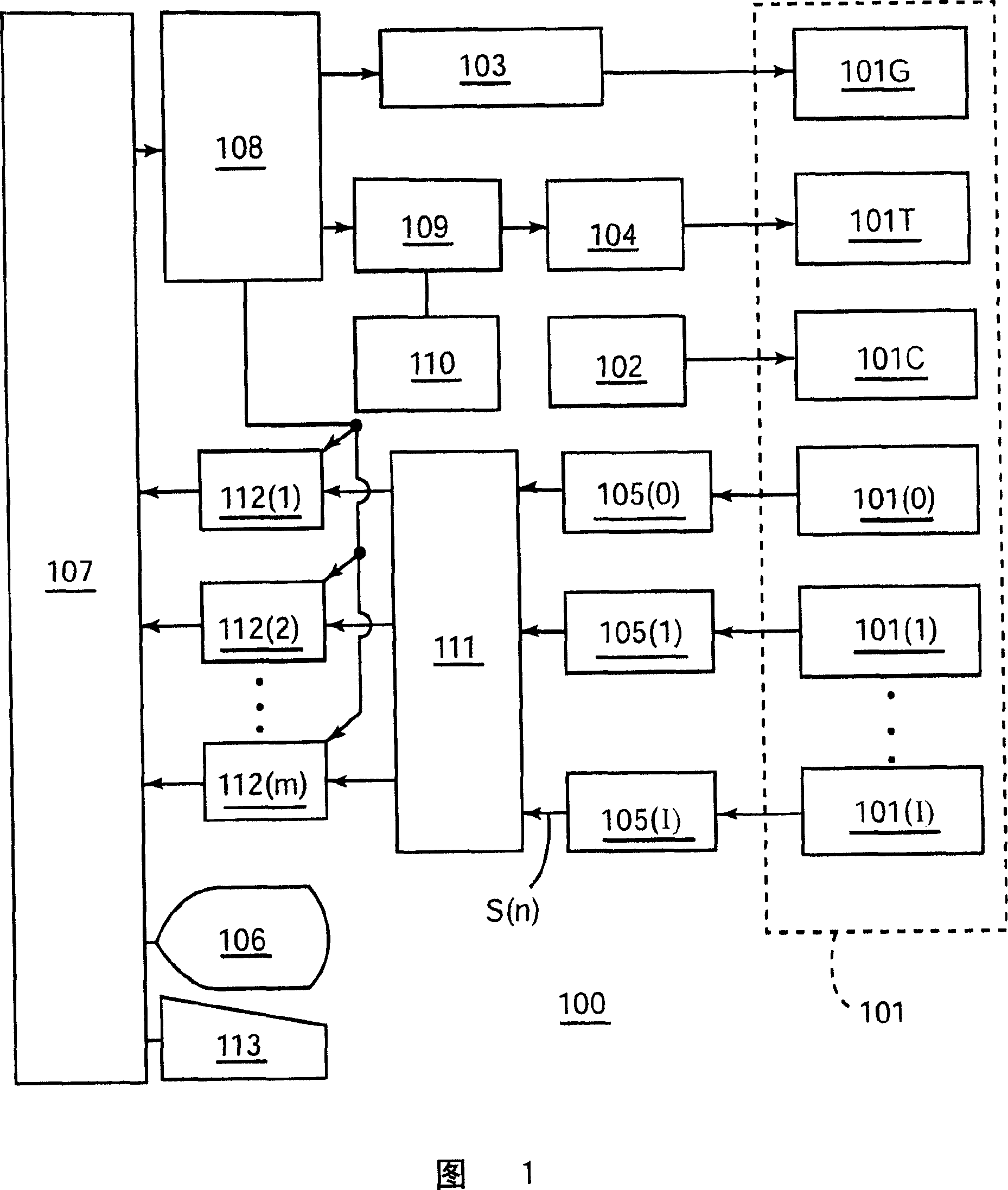
[0067] Referring now to FIG. 1 , there is shown a schematic block diagram representing an MRI apparatus 100 according to a first preferred embodiment of the present invention.

[0068] In this MRI apparatus 100, a magnet assembly 101 includes a central cavity (bore) for bearing an object therein. Arranged around the bore is a static magnetic field coil 101C for applying a constant static field to the object, a gradient coil 101G for generating a gradient field in the directions of the X, Y and Z axes, and a transmitting coil 101T for transmitting RF pulses, wherein The pulses are used to excite the spins of atomic nuclei within the subject for a plurality of receive coils 101(0)...101(I) for receiving NMR signals from the subject.

[0069] Transmitting coil 101T and receiving coil 101(0) are body coils, while receiving coils 101(1)...101(I) are surface coils.

[0070] The static magnetic field coil 101C, the gradient coil 101G, and the transmitting coil 101T are respectively ...


PUM


Abstract

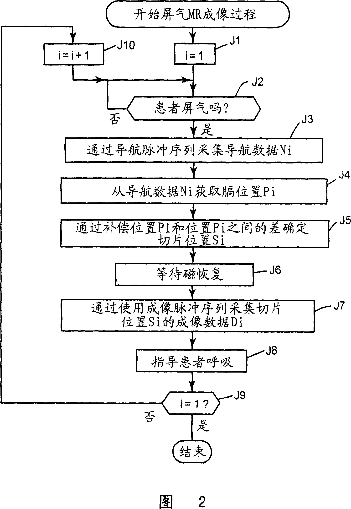
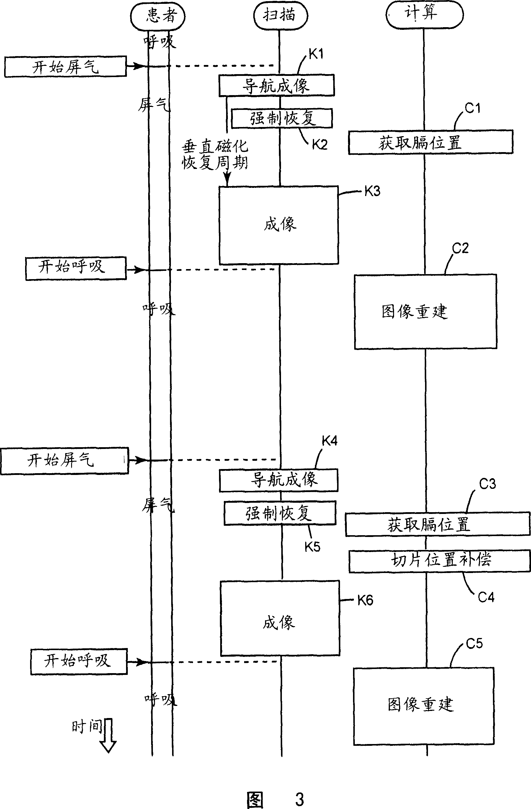
When two or more run of breath holding imaging with breathing interval therebetween is conducted, the present invention allows the slice position to follow the positional displacement of organ in each run. The present invention comprises an image capturing step for the navigator for imaging an MR image having the imaging area including the diaphragm during breath holding, a diaphragm position obtaining step for obtaining the diaphragm position by analyzing the navigator image, an image capturing step for the actual imaging for capturing an MR image of a desired slice during breath holding, and a breathing interval step for releasing respiration, in which these steps are iteratively repeated for twice or more. The slice position of second session or later is made to be a position which is set such that the slice position of first run is compensated for by the difference between the diaphragm position of the first run and the diaphragm position of the second run or later.

Description

technical field [0001] The present invention relates to a breath-hold MR (magnetic resonance) imaging method, an MRI (magnetic resonance imaging) device, a breath-hold tomography imaging method, and a tomography imaging device, more particularly to such a breath-hold MR (magnetic resonance) imaging method, MRI ( magnetic resonance imaging) devices, breath-hold tomography imaging methods, and tomographic imaging devices that allow slice positions according to displacement of organs between repeated imaging sessions of two or more breath-hold imaging with expiration times in between. Background technique [0002] So far, when two or more breath-hold imaging sessions have an expiratory interval in between, a method has been proposed that uses observation of the position of the diaphragm to guide the breath-hold while the diaphragm is in the same position (e.g. cite below Patent Document 1). [0003] On the other hand, when performing non-breath-hold imaging (during non-breath-...

Claims


Application Information

Patent Timeline
Patent Type & Authority Applications(China)
IPC IPC(8): A61B5/055G01R33/28G01R33/48
CPCG01R33/5676G01R33/56509
Inventor 岩馆雄治野崎敦塚元铁二椛泽宏之
Owner GE MEDICAL SYST GLOBAL TECH CO LLC
Learn More