Image processing apparatus and method for controlling the same

a technology of image processing and apparatus, applied in the field of image processing system, can solve the problems of difficult operation of operators, difficult quantification at expected accuracy level, and difficulty in manually designing the boundary of target layer boundary, etc., to accurately estimate the normal structure of the layer

Active Publication Date: 2010-09-02
CANON KK
View PDF6 Cites 85 Cited by
  • Summary
  • Abstract
  • Description
  • Claims
  • Application Information

AI Technical Summary

Benefits of technology

[0027]The present invention is directed to a mechanism that can accurately estimate a normal structure of a layer that constitutes an object.

Problems solved by technology

However, the work for manually designating the boundary of the target layer is not easy for an operator (e.g., a physician or an engineer).
Further, the work for manually designating the boundary of the target layer tends to generate a dispersion that results from differences of individual operators as well as differences in work date and time.
Therefore, performing quantification at an expected accuracy level was difficult.
On the other hand, because the above-described normal structure cannot be observed as image features on the tomographic image, the normal structure cannot be estimated using the technique discussed in Japanese Patent Application Laid-Open No. 2008-73099 or in Japanese Patent Application Laid-Open No. 2007-325831.
However, the work for manually designating a layer boundary is not easy for an operator (e.g., a physician or an engineer).
Further, the work for manually designating the boundary of the target layer tends to generate a dispersion that results from differences of individual operators as well as differences in work date and time.
Therefore, performing quantification at an expected accuracy level was difficult.
On the other hand, because the above-described normal structure cannot be observed as image features on the tomographic image, the normal structure cannot be estimated using the technique discussed in the above-described patent literatures.
However, the above-described normal structure having been estimated by applying an elliptic curve according to the conventional least squares method tends to be greatly different from the actual normal structure.
Therefore, even if an area is obtainable as a difference between the normal structure and a detected layer boundary, the obtained area cannot be used as a reliable index that can quantify the state of a disease.
Namely, acquiring the image features of the boundary 1005 of the retinal pigment epithelium may partly fail due to the influence of such an obstacle.

Method used


Image

  • Image processing apparatus and method for controlling the same
  • Image processing apparatus and method for controlling the same
  • Image processing apparatus and method for controlling the same

Examples


first modified example

[0242]A first modified example according to the present exemplary embodiment is described below. In the above-described exemplary embodiments, the normal structure estimation unit 2520 estimates a normal structure of a predetermined layer using the least squares method or the M estimation method in the processing of step S3030 illustrated in FIG. 17. However, the normal structure estimation method is not limited to the above-described methods. For example, the normal structure estimation unit 2520 can obtain a conversion matrix that maximizes an evaluation reference that is the number of points (inliers) where the difference εi of the formula (1) is equal to or less than a predetermined threshold.

[0243]Further, the detected boundary 1005 of the retinal pigment epithelium and all points of the normal state data are used in the normal structure estimation processing performed in step S3030 illustrated in FIG. 17. However, the number of points to be used in the above-described processi...


PUM


Abstract

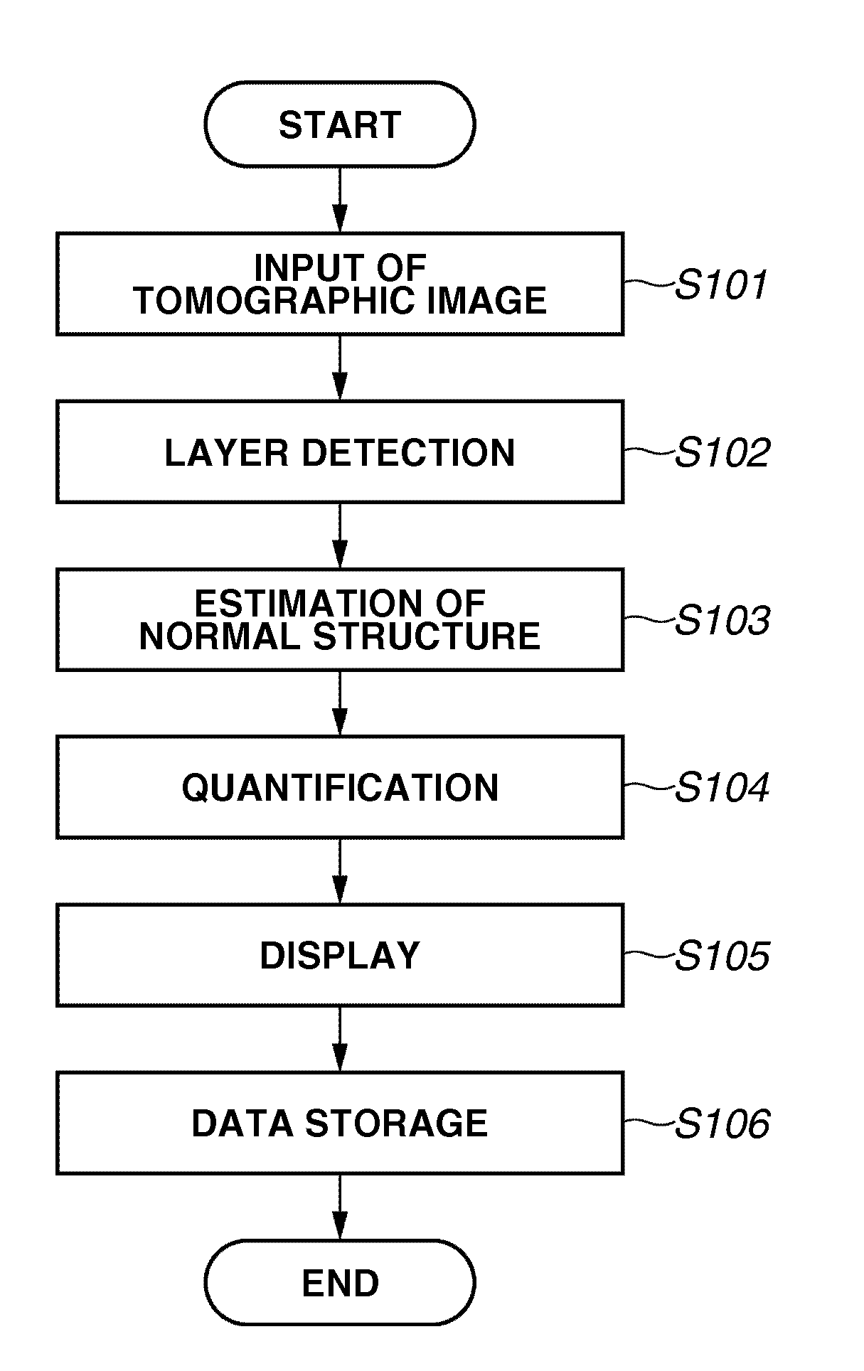
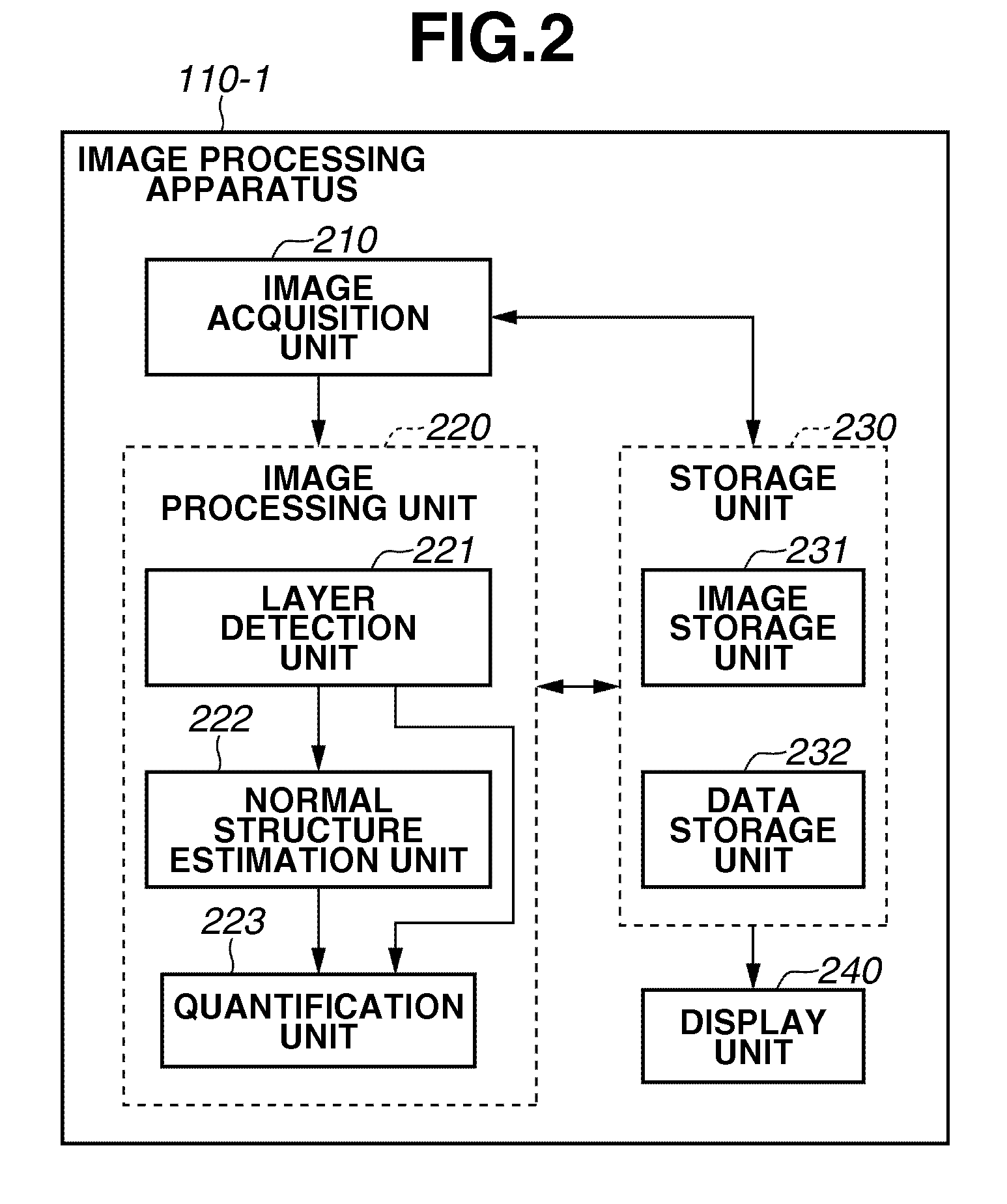
An image processing apparatus includes an image acquisition unit configured to acquire a tomographic image of an object, a layer detection unit configured to detect a layer that constitutes the object from the tomographic image acquired by the image acquisition unit, and a normal structure estimation unit configured to estimate a normal structure of the layer based on the layer detected by the layer detection unit and a feature that is modified by a lesion of the layer.

Description

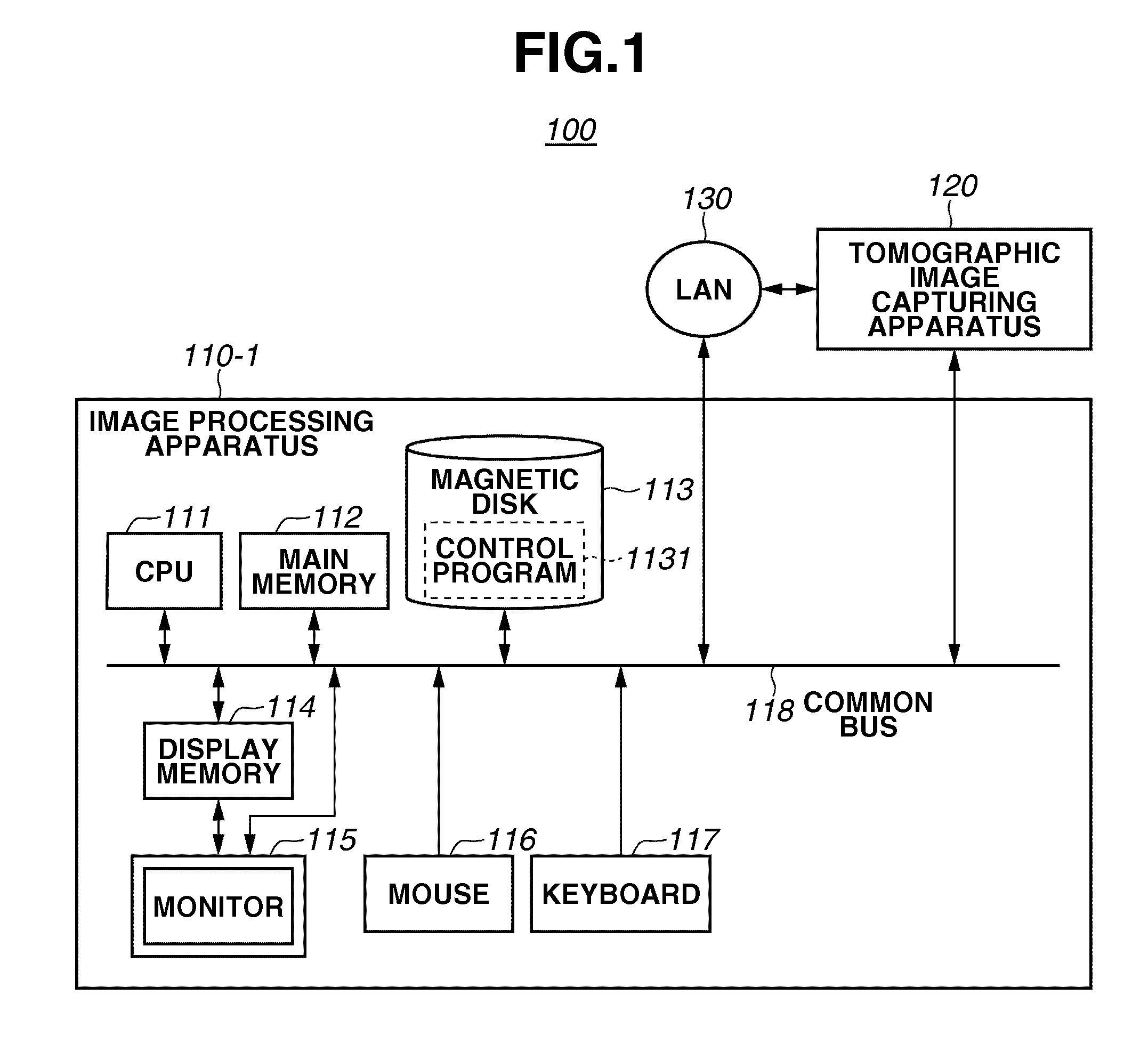
BACKGROUND OF THE INVENTION[0001]1. Field of the Invention[0002]The present invention relates to an image processing system for processing a tomographic image of an object.[0003]2. Description of the Related Art[0004]To diagnose lifestyle related diseases and other various diseases, which may lead to blindness, in their early stages, inspections are conventionally performed based on captured images of eye portions (i.e., objects). For example, a tomographic image acquiring apparatus using an Optical Coherence Tomography (hereinafter, referred to as “OCT”) can be used to observe a three-dimensional state of an internal retinal layer of an eye portion. Therefore, the tomographic image acquiring apparatus is expected to be a prospective diagnosis apparatus that can accurately diagnose various diseases.[0005]In a cross-sectional layer image (i.e., a tomographic image) of an eye portion obtained using the OCT, the stage of a disease (e.g., glaucoma, age-related macular degeneration, and ...

Claims


Application Information

Patent Timeline
Patent Type & Authority Applications(United States)
IPC IPC(8): G06K9/00
CPCA61B5/0066A61B5/0073G06T2207/30041G06T7/0012G06T2207/10072G06K2209/05G06V2201/03
Inventor IWASE, YOSHIHIKOUCHIYAMA, SHINJISATOH, KIYOHIDE
Owner CANON KK
Why Eureka
Try Eureka