

Foam pushing device of floatation machine
A flotation machine and a set of technology, applied in the direction of flotation, solid separation, etc., can solve the problems of easy flow of foam, easy stagnation of foam, falling off of foam particles, etc., to improve the flotation index, shorten the conveying distance, and achieve good flotation effect. Effect
- Summary
- Abstract
- Description
- Claims
- Application Information
AI Technical Summary
Problems solved by technology
Method used
Image

Examples
Embodiment Construction
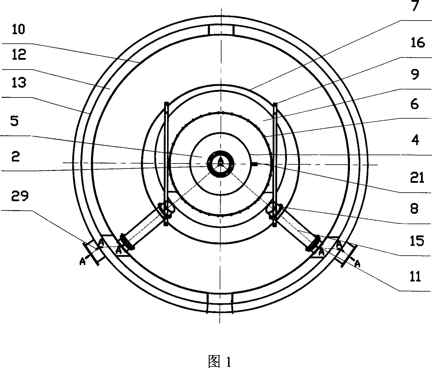
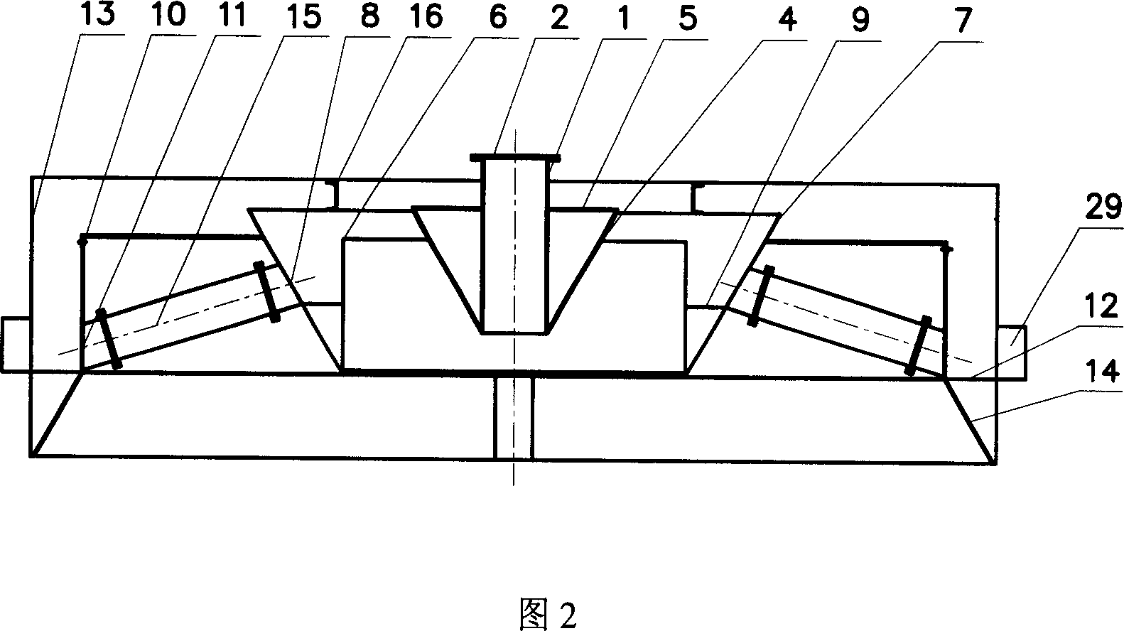
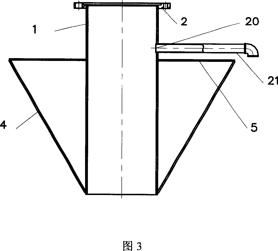
[0036] A foam pushing device of a flotation machine, the foam pushing device is a double foam pushing cone structure composed of an inner foam pushing cone, an inner foam groove, an outer foam cone complex, and an outer foam groove; wherein the structure of the inner foam pushing cone Including: connecting pipe 1-the connecting pipe is a tube-shaped structure that is fitted on the hollow main shaft of the flotation machine with a coaxial gap, and the upper end is fixed on the bearing body 3 at the upper end of the main shaft through the flange 2; the inner push bubble cone panel 4- The cone panel is an annular truncated cone plate, and the bottom ring edge of the truncated cone is fixedly connected to the bottom edge of the connecting pipe; the angle between the truncated cone plate and the connecting pipe surface is 25°~45°; the horizontal sealing plate 5-the sealing plate is horizontal Ring plate; its inner ring edge is fixedly connected to the wall of the connecting pipe, an...
PUM
 Abstract
Description
Claims
Application Information