Weight gravity tester
A technology of weight and gravity, which is applied in the field of electronic product testing equipment, can solve the problems such as the inability to obtain the test quality of the pressing force button, the inability to have a correct indicator, and the irregular force, etc., to achieve fast test speed and facilitate large-scale modernization The effect of production and quality assurance
- Summary
- Abstract
- Description
- Claims
- Application Information
AI Technical Summary
Problems solved by technology
Method used
Image
Examples
Embodiment 1
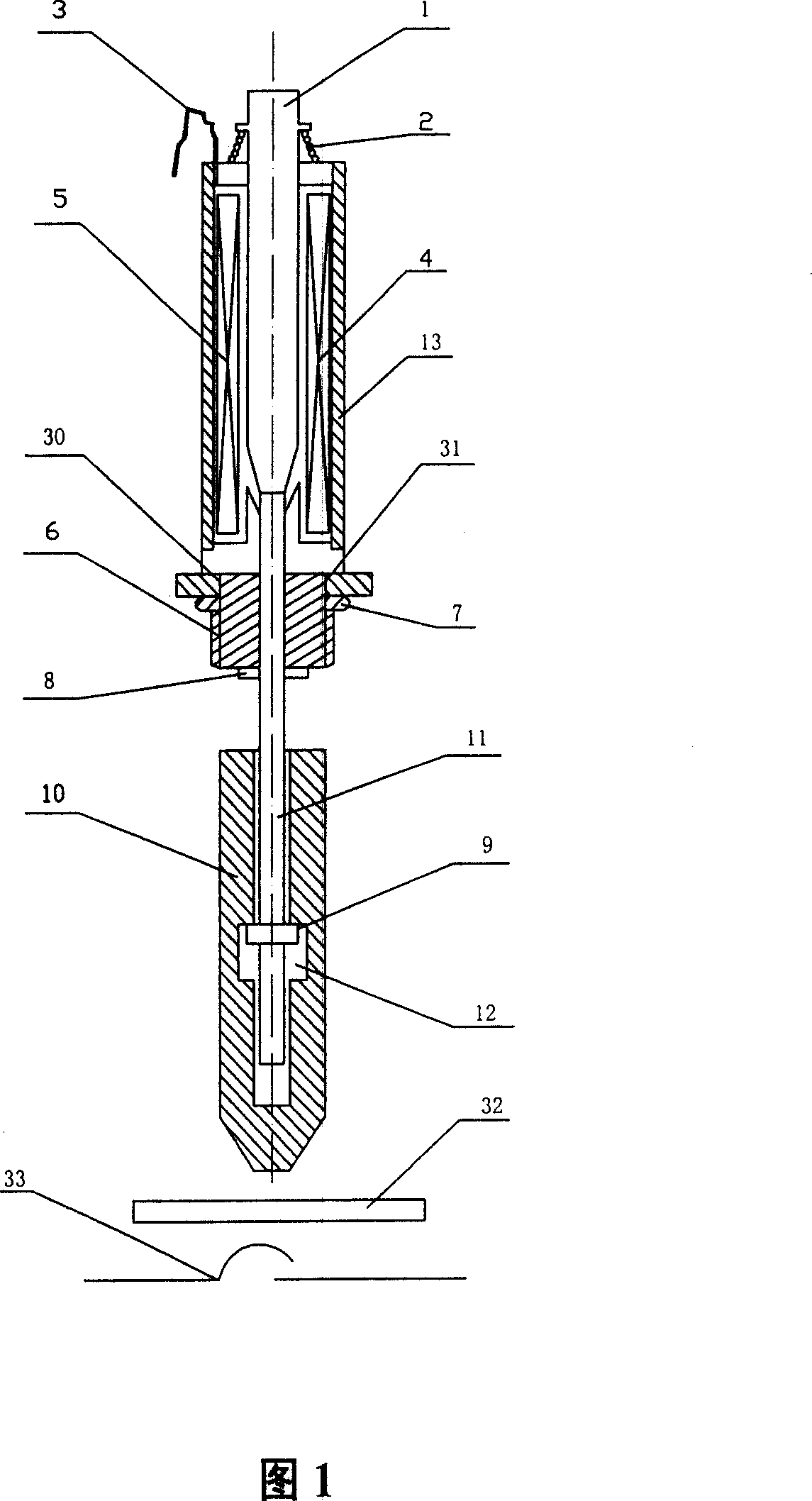
[0018] Embodiment 1: It can be clearly seen from Fig. 1 that this is an electromagnetically driven single-set weight gravity finger. The so-called "single-weight gravity finger" means setting a weight on the test weight gravity finger. The weight gravity finger of the single group is composed of a shaft 1 , a weight 10 , an electromagnetic drive mechanism 4 , a shaft return spring 2 and a mounting seat 6 . The middle part of the shaft 1 is provided with a first limit buckle 8, and the end is provided with a second limit buckle 9; the weight 10 is a tapered cylinder, and its center is provided with a shaft hole 11 for the shaft 1 to be introduced into. , the shaft hole 11 is provided with a section of the limit section 12 for the second limit buckle 9 on the shaft 1 to move up and down; Line 3 is composed. The top of the shaft 1 is inserted into the cylindrical coil 5 of the electromagnetic drive mechanism 4, the top of the shaft 1 is provided with a return spring 2 connected ...
Embodiment 2
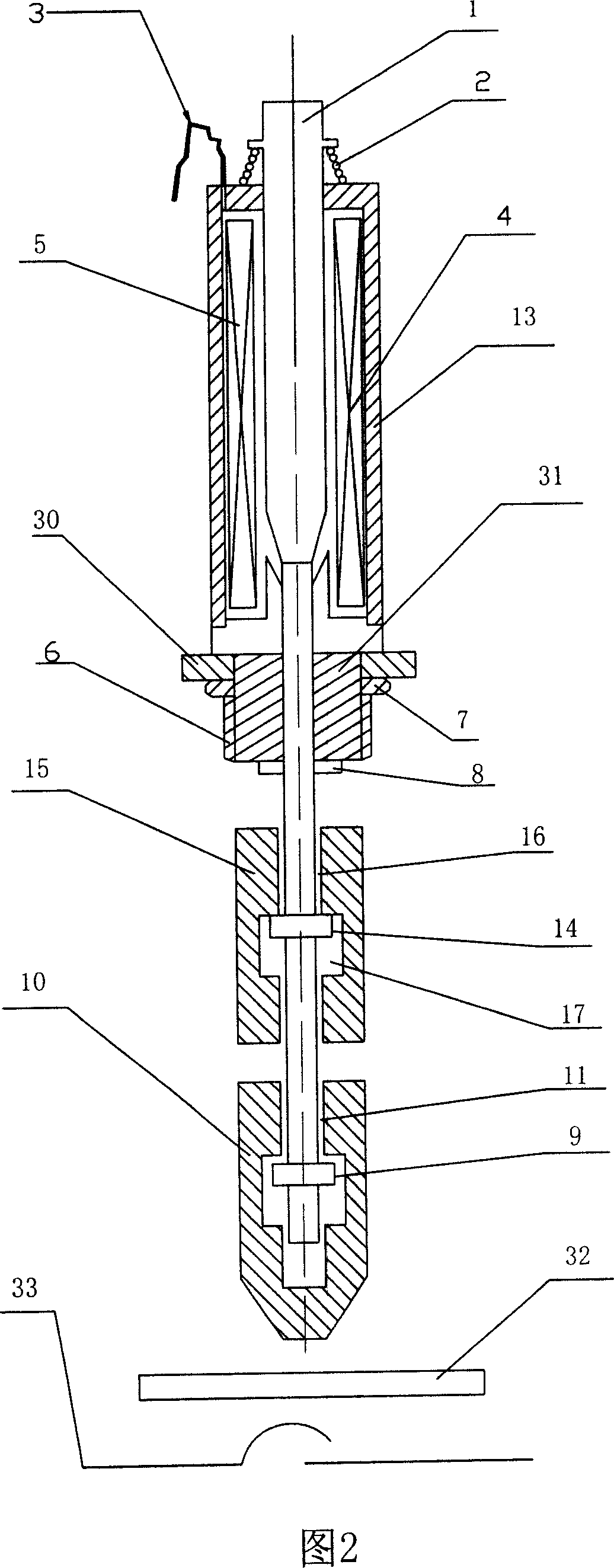
[0025] Embodiment 2: It can be clearly seen from Fig. 2 that this is an electromagnetically driven double-weight gravity finger. The so-called "two-group weight gravity finger" is exactly to set two weights on the weight gravity finger. The basic structure of this "double weight gravity finger" is the same as that of Embodiment 1, the only difference being that an upper weight 15 is added in the middle of the shaft 1 . That is: add a third limit buckle 14 in the middle of the shaft 1, add an upper weight 15 to the shaft 1 at the third limit buckle 14, and the upper weight 15 is columnar, with a hole in the center for the shaft 1 to shuttle. Shaft hole 16, the shaft hole 16 is provided with a limit interval 17 that cooperates with the third limit buckle 14 on the shaft rod 1, and the upper weight 15 can move up and down along the shaft rod 1 within the range of the limit interval 17.
[0026] The working process of the electromagnetically driven double weight gravity finger is...
Embodiment 3
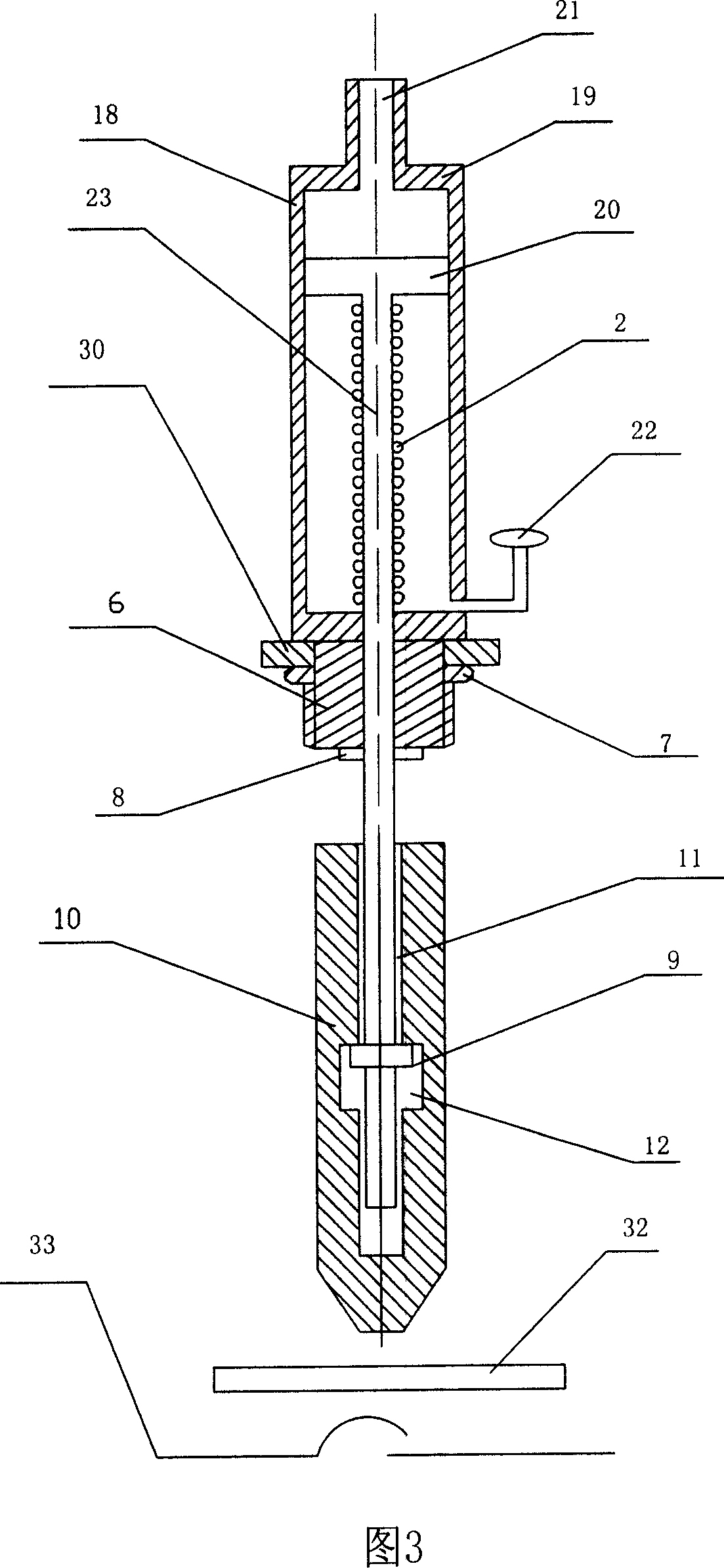
[0032] Embodiment 3: It can be clearly seen from Fig. 3 that this is a cylinder-driven single-set weight gravity finger. Its basic structure is the same as that of Embodiment 1, the only difference is that the driving mechanism is the cylinder driving mechanism 18 . The cylinder driving mechanism 18 is composed of a cylinder body 19 and a piston rod 20 disposed therein, and an upper air inlet 21 and a lower air inlet 22 are provided at both ends of the cylinder body 19 . The piston rod 23 protrudes from one end of the cylinder body 19 to become a shaft rod for weight installation, and the cylinder driving mechanism 18 impels the piston rod 23 to move downward. A reset spring 2 can be sleeved on the piston rod 23 inside the cylinder body 19 .
[0033] The piston 20 in the cylinder 19 is driven to move up and down by controlling the air volume input to the upper and lower air inlets 21 and 22 at both ends of the cylinder 19 of the cylinder driving mechanism 18, and then drives ...
PUM
 Abstract
Description
Claims
Application Information
 - R&D
- Intellectual Property
- Life Sciences
- Materials
- Tech Scout
- Unparalleled Data Quality
- Higher Quality Content
- 60% Fewer Hallucinations
Browse by: Latest US Patents, China's latest patents, Technical Efficacy Thesaurus, Application Domain, Technology Topic, Popular Technical Reports.
© 2025 PatSnap. All rights reserved.Legal|Privacy policy|Modern Slavery Act Transparency Statement|Sitemap|About US| Contact US: help@patsnap.com


