Optical film and liquid crystal display device
A technology of liquid crystal display device and optical film, applied in optics, optical elements, nonlinear optics, etc., can solve the problems of display darkening and productivity deterioration.
- Summary
- Abstract
- Description
- Claims
- Application Information
AI Technical Summary
Problems solved by technology
Method used
Image
Examples
Embodiment 1
[0153] (optical film)
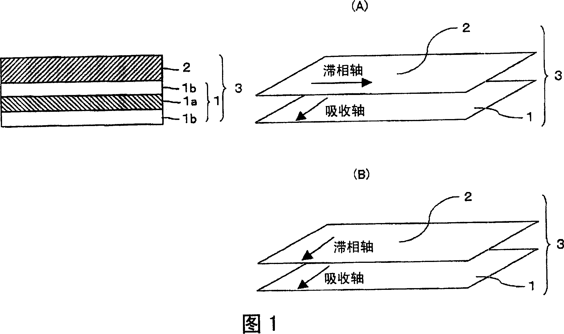
[0154] The polycarbonate film is stretched at 150°C under the adhesion of a heat-shrinkable film to obtain a thickness of 45 μm and an in-plane retardation Re 2 It is a retardation film of 140 nm and Nz=0.5. The retardation film and the composite absorbing polarizer were laminated with an acrylic adhesive so that the slow axis of the retardation film and the absorption axis of the polarizer were perpendicular to each other, thereby producing an optical film.
[0155] (Liquid Crystal Display Device)
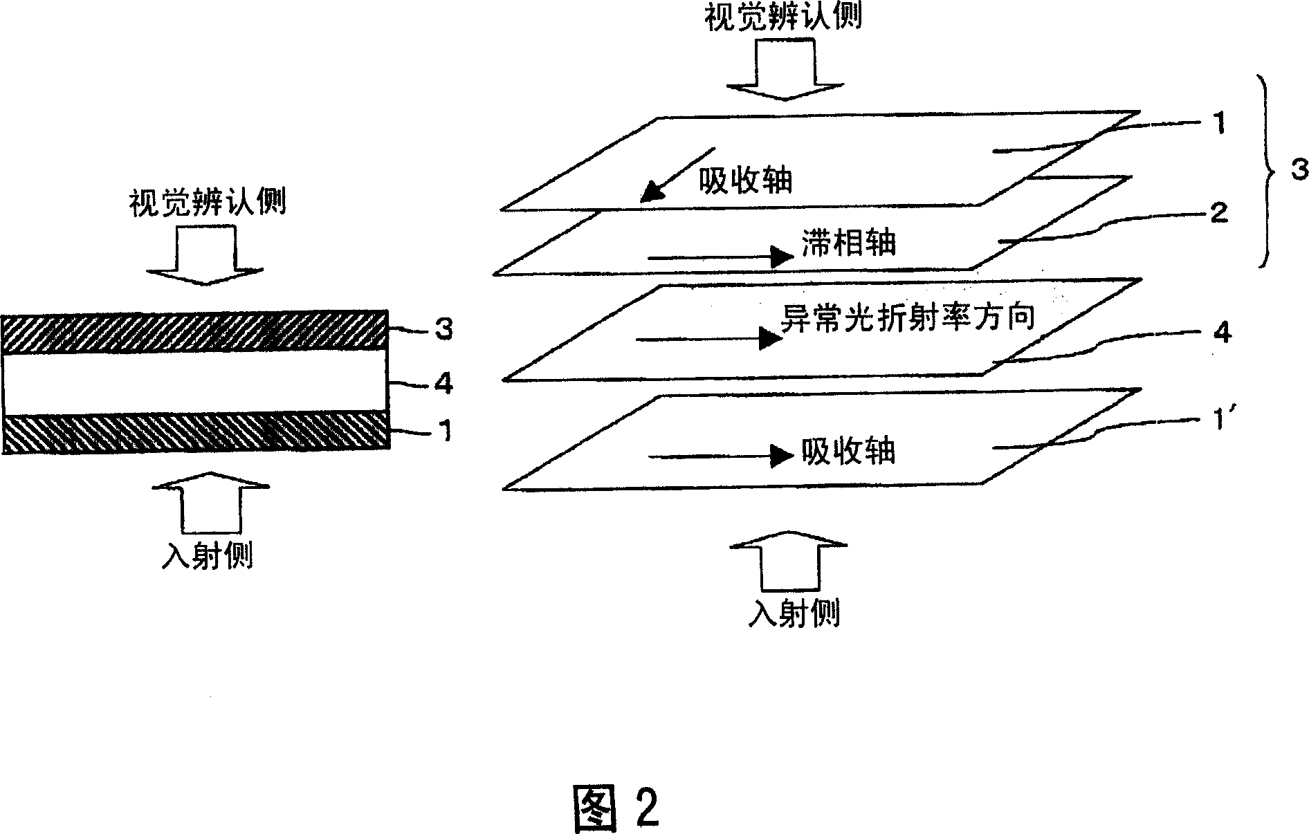
[0156]Using an IPS mode liquid crystal cell with a retardation value of 280 nm for 550 nm, as shown in FIG. On the other hand, the composite absorbing polarizing plate produced above was laminated with an acrylic adhesive on the surface opposite to the liquid crystal cell to produce a liquid crystal display device. The layers are stacked so that the absorption axis of the incident-side polarizing plate (optical film) is perpendicular to the direction of ...
Embodiment 2
[0158] (optical film)
[0159] The polycarbonate film is stretched at 150°C under the adhesion of a heat-shrinkable film to obtain a thickness of 45 μm and an in-plane retardation Re 2 It is a retardation film of 140 nm and Nz=0.3. Using an acrylic adhesive, this retardation film and the same absorbing composite polarizer as used in Example 1 were laminated so that the slow axis of the retardation film and the absorption axis of the polarizer were in a perpendicular state, thereby Make optical films.
[0160] (Liquid Crystal Display Device)
[0161] Using an IPS mode liquid crystal cell with a retardation value of 280 nm at 550 nm, as shown in FIG. 2 , an acrylic adhesive was laminated so that the retardation film side of the optical film was the viewing side of the IPS mode liquid crystal cell. On the other hand, the absorption composite polarizing plate produced above was laminated with an acrylic adhesive on the surface opposite to the liquid crystal cell to produce a li...
Embodiment 3
[0163] (Liquid Crystal Display Device)
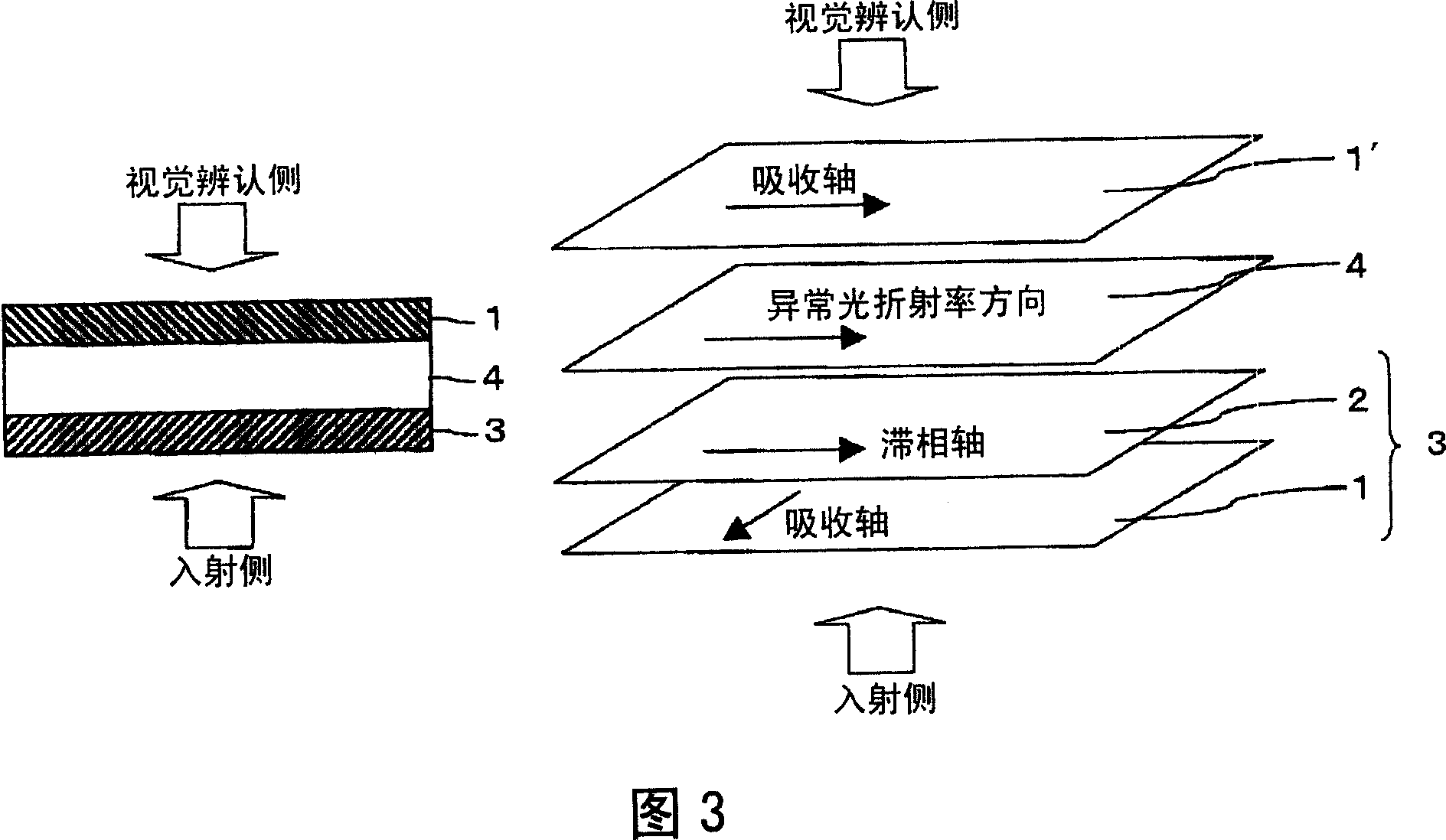
[0164] Using an IPS mode liquid crystal cell with a retardation value of 280 nm for 550 nm, as shown in FIG. The face on the incident side. On the other hand, a commercially available polarizing plate (NPF-SEG1224DU, manufactured by Nitto Denko Co., Ltd.) was laminated with an acrylic adhesive on the surface opposite to the liquid crystal cell to produce a liquid crystal display device. The layers are stacked so that the absorption axis of the incident-side polarizing plate (optical film) is perpendicular to the direction of the extraordinary light refractive index possessed by the liquid crystal in the liquid crystal cell. The slow axis of the retardation film (optical film) becomes parallel to the absorption axis of the viewing side polarizing plate. The absorption axis of the incident-side polarizing plate (optical film) and the absorption axis of the viewing-side polarizing plate are in a state of being perpendicular to each other...
PUM
| Property | Measurement | Unit |
|---|---|---|
| length | aaaaa | aaaaa |
| transition temperature | aaaaa | aaaaa |
| thickness | aaaaa | aaaaa |
Abstract
Description
Claims
Application Information
 - R&D
- Intellectual Property
- Life Sciences
- Materials
- Tech Scout
- Unparalleled Data Quality
- Higher Quality Content
- 60% Fewer Hallucinations
Browse by: Latest US Patents, China's latest patents, Technical Efficacy Thesaurus, Application Domain, Technology Topic, Popular Technical Reports.
© 2025 PatSnap. All rights reserved.Legal|Privacy policy|Modern Slavery Act Transparency Statement|Sitemap|About US| Contact US: help@patsnap.com


