Flat-board display of shallow-pit type cathode curved grid control structure and mfg. process

A flat-panel display and control structure technology, used in cold cathode manufacturing, control electrodes, electrode system manufacturing, etc.

A flat-panel display and control structure technology, used in cold cathode manufacturing, control electrodes, electrode system manufacturing, etc.

CN1937151AInactive Publication Date: 2007-03-28ZHONGYUAN ENGINEERING COLLEGE

Image

  • Flat-board display of shallow-pit type cathode curved grid control structure and mfg. process
  • Flat-board display of shallow-pit type cathode curved grid control structure and mfg. process

Examples


Embodiment Construction

[0037] The present invention will be further described below in conjunction with the accompanying drawings and embodiments, but the present invention is not limited to these embodiments.

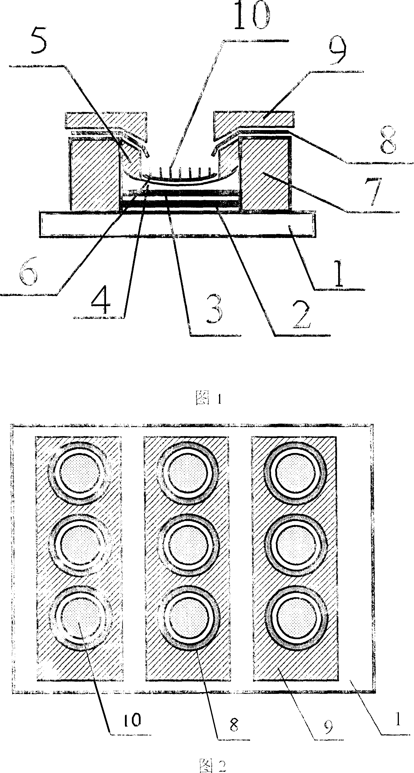
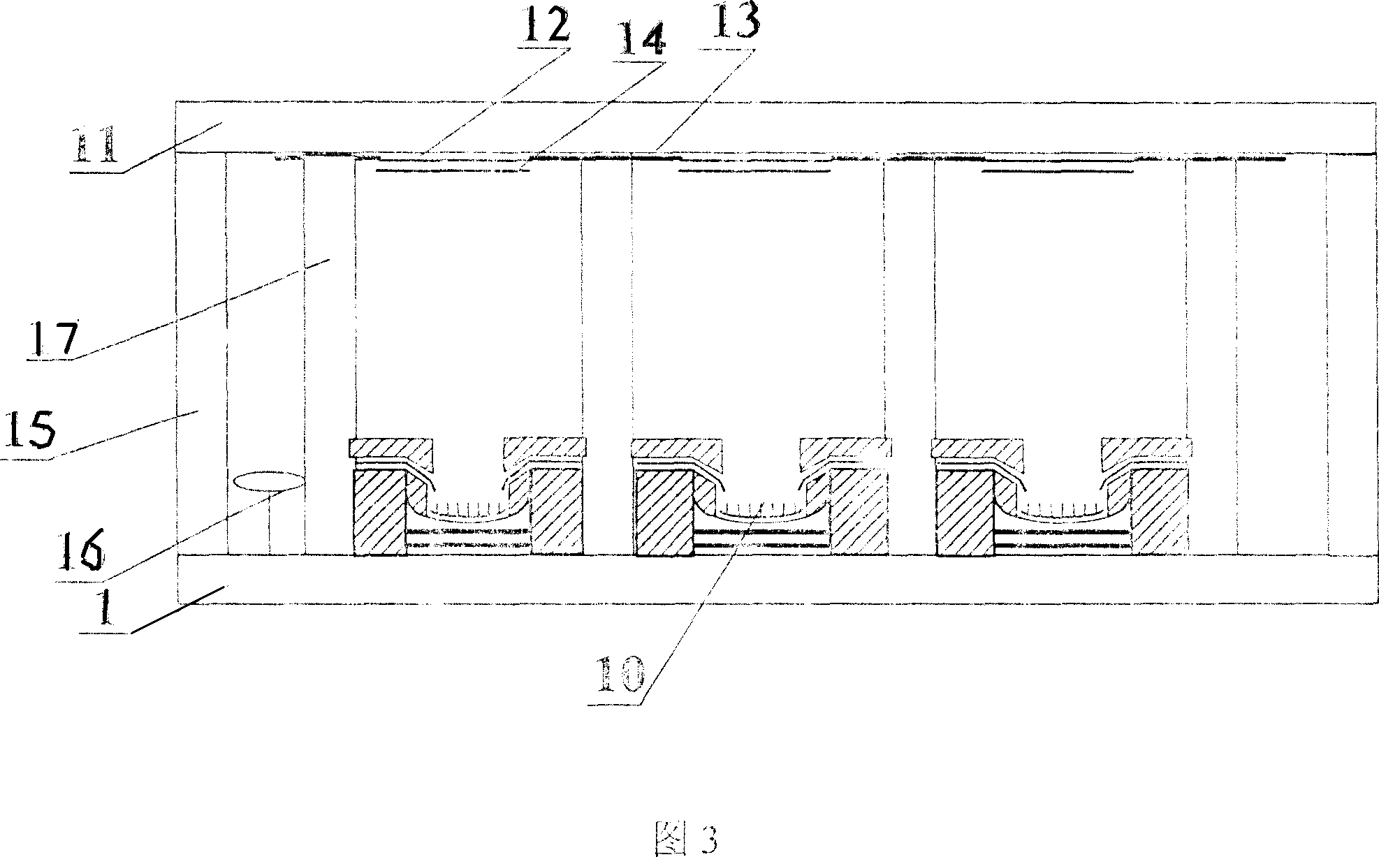
[0038]The flat-panel display with shallow dimple type cathode curved grid control structure includes a sealed vacuum chamber composed of a cathode glass panel [1], an anode glass panel [11] and surrounding glass frames [15]; The anode glass panel has an anode conductive layer [12] and a phosphor layer [14] prepared on the anode conductive layer; a support wall structure [17] between the anode glass panel and the cathode glass panel and getter accessories [16 ], on the cathode glass panel there is a cathode conductive layer [6], carbon nanotubes [10] and a concave cathode curved grid control structure.

[0039] The shallow dimple type cathode curved grid control structure includes cathode glass panel [1], insulating layer [2], cathode lead layer [3], cathode lifting layer [4], cathode coverin...


PUM


Abstract

The flat panel display includes cathode glass faceplate, anode glass faceplate, and sealed vacuum cavity surrounded by glass frame. There are cathode conductive layer, Nano carbon tubes, and sink marks type structure of curved grid electrode control structure of cathode on the cathode glass faceplate. There are anode conductive layer and phosphor layers prepared on the conductive layer on anode glass faceplate. Structure of supporting wall and attached elements of getter are located between anode glass faceplate and cathode glass faceplate. The invention enhances control function of grid electrode, integrates structure of grid electrode-cathode and reduces working voltage of apparatus so as to be in favor of raise display brightness of whole apparatus. Advantages are: stable and reliable manufacturing procedure, simple technique and structure, and low cost.

Description

technical field [0001] The invention belongs to the fields of flat panel display technology, microelectronic science and technology, vacuum science and technology, and nano science and technology, and relates to device fabrication of flat panel field emission displays, in particular to carbon nanotube cathodes. The device manufacturing aspect of the flat field emission display, especially relates to a flat panel display with a shallow dimple cathode curved grid control structure and its manufacturing process. Background technique [0002] Carbon nanotubes have a small tip curvature radius, high aspect ratio, and can exhibit excellent field emission characteristics under the action of an applied electric field strength, and are very suitable for use as cold cathode materials for field emission display devices. As a man-machine communication interface and information display, flat-panel displays are closely related to people's lives. Flat-panel displays will quickly replace tr...

Claims


Application Information

Patent Timeline
28 Mar 2007
Publication
CN1937151A
IPC
H01J29/02; H01J29/04; H01J29/46; H01J1/304; H01J1/46; H01J31/12; H01J9/02; H01J9/00
Inventors
李玉魁