
Coating apparatus, organic material thin film forming method and organic el panel manufacturing apparatus

A coating device and organic material technology, applied to the surface coating liquid device, printing device, lighting device, etc., can solve the problems of violating space saving and high cost, and achieve the effect of shortening the working time

Inactive Publication Date: 2007-03-28
ULVAC INC
View PDF2 Cites 4 Cited by
  • Summary
  • Abstract
  • Description
  • Claims
  • Application Information

AI Technical Summary

Problems solved by technology

[0013] An apparatus for forming an organic thin film using an inkjet printer as described above is described in the following documents, but the following organic EL panel manufacturing apparatus requires both a heating chamber and a cooling chamber, which not only violates the principle of saving space, but also, high cost

Method used


Image

  • Coating apparatus, organic material thin film forming method and organic el panel manufacturing apparatus
  • Coating apparatus, organic material thin film forming method and organic el panel manufacturing apparatus
  • Coating apparatus, organic material thin film forming method and organic el panel manufacturing apparatus

Examples


Embodiment Construction

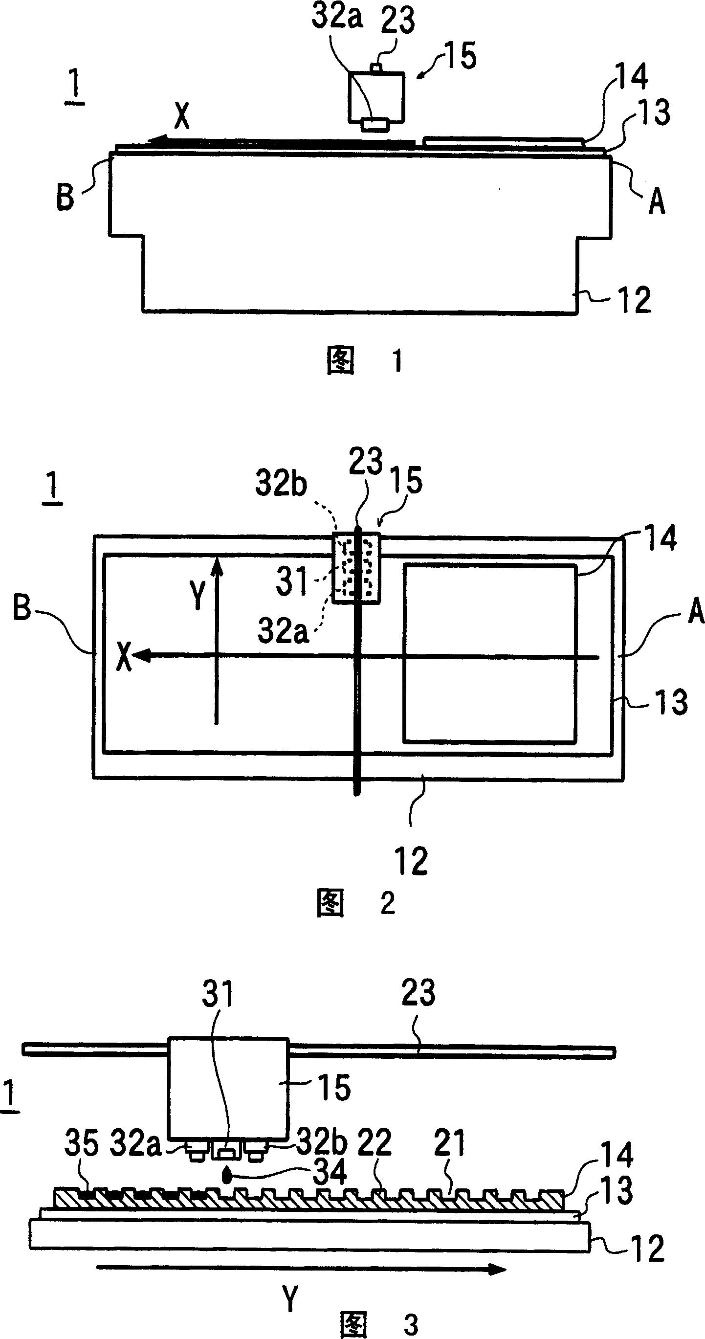
[0047] Reference numeral 1 in FIG. 1 denotes a coating device of a first example of the present invention.

[0048] The coating device 1 has a coating station 12 . A substrate conveyance mechanism 13 is provided on the coating stage 12, and by the operation of the substrate conveyance mechanism 13, the object 14 to be coated on the coating stage 12 can be moved along the longitudinal direction of the coating stage 12 from The movement source A side of the coating table 12 moves toward the movement destination B. As shown in FIG. That is, in the movement of the object to be coated 14, the movement source A is on the upstream side, and the movement destination B is on the downstream side.

[0049] A head moving mechanism 23 is arranged above the coating table 12 , and a movable head 15 is attached to the head moving mechanism 23 . By the operation of the head moving mechanism 23 , the head 15 can reciprocate in a direction substantially perpendicular to the direction of moveme...


PUM


Abstract

A coating apparatus which does not require a heating chamber nor a cooling chamber is provided. An object (14) to be coated moves in an X axis direction, and on the object, an ejector (31) and laser irradiation apparatuses (32a, 32b), which can reciprocate in a Y axis direction, are arranged. An organic material ejected on a part of the surface of the object (14) from the ejector (31) is irradiated with laser beams, dried or polymerized by heating, and formed into a thin film. Moving of the ejector (31) and the laser irradiation apparatuses (32a, 32b) in the Y axis direction and moving of the object (14) in the X axis direction are repeatedly performed, and a thin film made of the organic material is formed on a prescribed region of the object (14). Since coating and laser beam irradiation can be performed parallel, operation efficiency is high. Further, since the temperature of the object (14) does not become high, a cooling process is not required.

Description

technical field [0001] The invention relates to a technology for forming an organic thin film, in particular to a coating device for forming a film by means of inkjet. Background technique [0002] In order to form an organic thin film used in an organic EL panel, a technique using a coating device such as an inkjet printer has been developed. [0003] Reference numeral 100 of FIG. 8 is a prior art organic EL panel manufacturing device, and reference numeral O 1 ~O 4 This is a coating device that forms an organic thin film on the surface of a substrate by the inkjet method. Here, in the first to fourth coating devices O 1 ~O 4 Inside, organic materials for forming a hole transport layer, a red layer, a green layer, and a blue layer are arranged respectively. [0004] Reference sign T 1 ~T 5 It is the first to fifth transport chambers for transporting substrates, in each transport chamber T 1 ~T 5 The interior of the substrate is equipped with a substrate conveying r...

Claims


Application Information

Patent Timeline
IPC IPC(8): H05B33/10B05C9/14B05C5/00H01L51/50
CPCH01L51/56B41J11/002H01L51/0027H01L51/0005B41J11/0021B41J3/407H10K71/135H10K71/421H10K71/441
Inventor 根岸敏夫
Owner ULVAC INC
Features
  • Generate Ideas
  • Intellectual Property
  • Life Sciences
  • Materials
  • Tech Scout
  • Unparalleled Data Quality
  • Higher Quality Content
  • 60% Fewer Hallucinations
Learn More