
Impurity treating apparatus

A treatment device and inclusion technology, applied in water supply equipment, water/sewage treatment, grease/oily substance/floating matter removal device, etc., can solve the problems of large water flow resistance, hindering the passage of sewage, and difficult removal of inclusions, etc. Achieving reduced water flow resistance, efficient and reliable collection, and increased durability

Active Publication Date: 2007-04-04
SUMITOMO HEAVY INDUSTRIES ENVIRONMENT CO LTD
View PDF2 Cites 28 Cited by
  • Summary
  • Abstract
  • Description
  • Claims
  • Application Information

AI Technical Summary

Problems solved by technology

The screen part of the mesh screen 2 moving on a substantially elliptical orbit is made of a flexible material such as polyethylene / nylon, so it is difficult to make the screen part strong, and the screen part is easily damaged, resulting in poor durability.
In addition, the sieve is an infinite circulation type, so the sieve is double-layered and the water flow resistance is large, which will hinder the passage of sewage, and the inclusions that have passed the front side are difficult to discharge from the rear side and remain inside the sieve. have trouble running
In addition, since the sieve is a belt surface woven into a net shape, the inclusions are easily caught by the unevenness, and once the inclusions are caught, it is difficult to untie the problem.
[0007] In addition, in the device described in Patent Document 2, as the water flow becomes faster, the component force in the flow direction of the water flow is too large compared with the component force that moves the inclusions along the grid screen, and the inclusions will be squeezed on the grid screen. The problem of stagnation due to not being able to move along the grid screen

Method used


Image

  • Impurity treating apparatus
  • Impurity treating apparatus
  • Impurity treating apparatus

Examples


Embodiment Construction

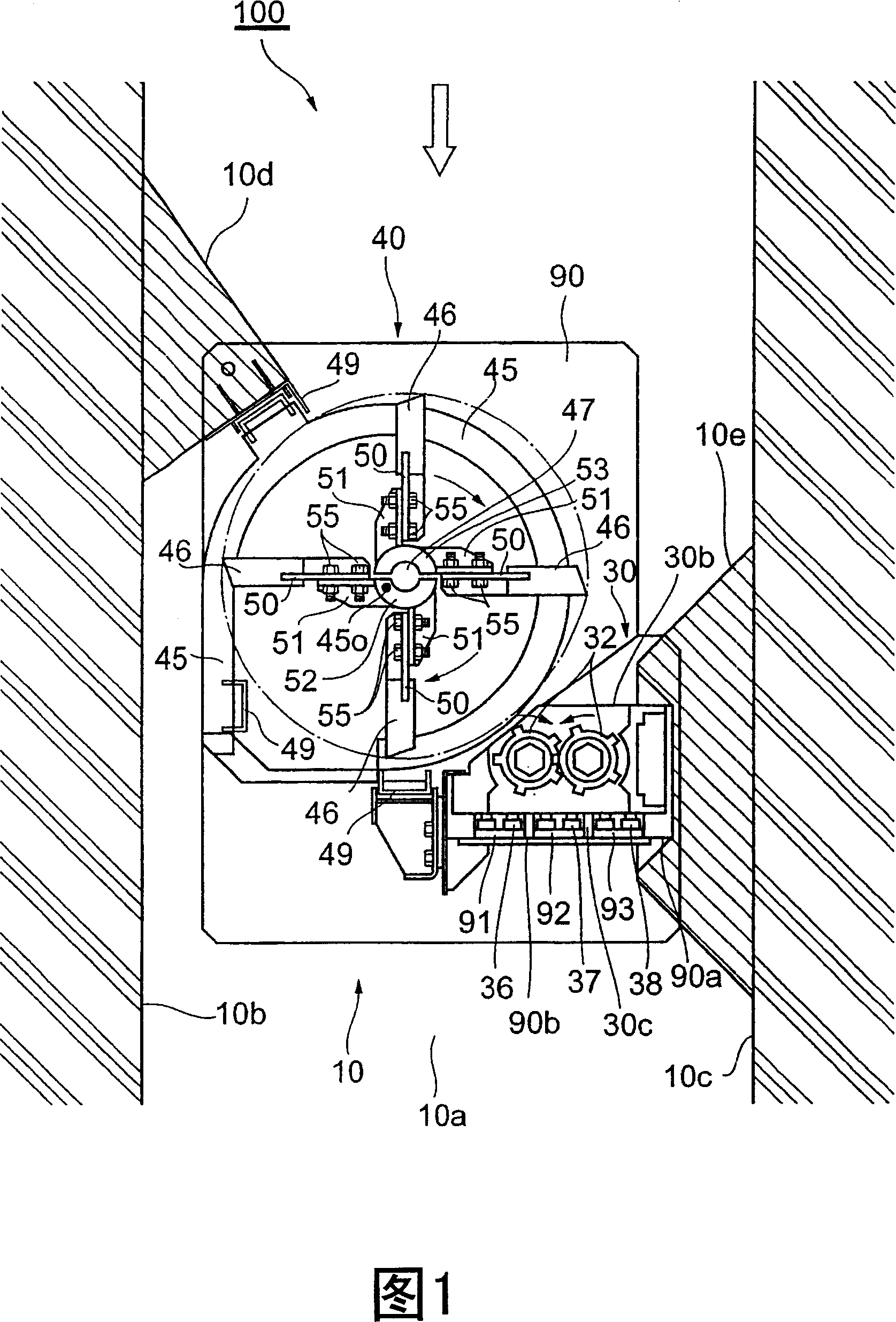
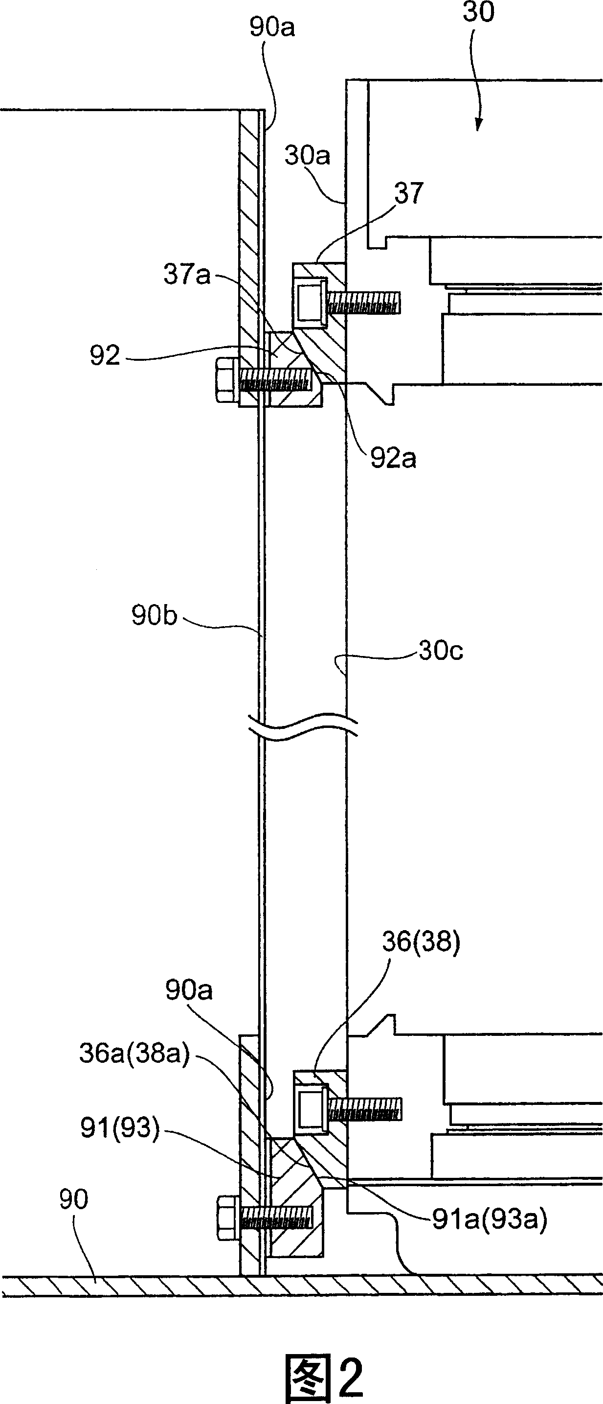
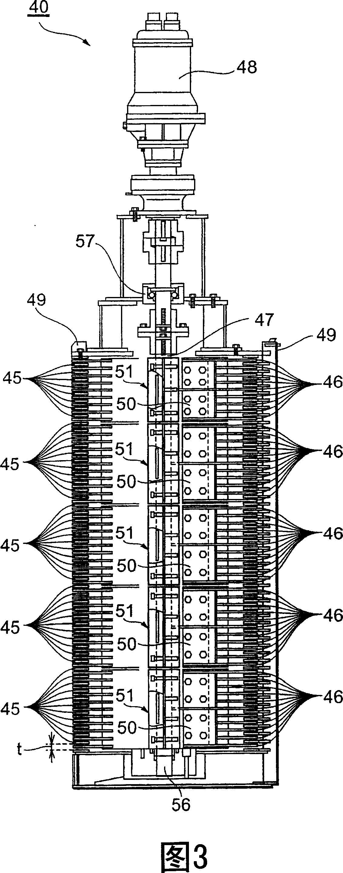
[0025] Next, preferred embodiments of the inclusion processing apparatus of the present invention will be described with reference to the accompanying drawings. In addition, in the description of the drawings, the same or corresponding elements are given the same reference numerals, and repeated descriptions are omitted. Fig. 1 shows a plan view of an inclusion processing device according to an embodiment of the present invention, Fig. 2 is a schematic sectional view showing the installation of a wedge-shaped liner in Fig. 1 , and Fig. 3 is a longitudinal sectional view showing a screen device in Fig. 1 , and Fig. 4 is a plan view showing the rake in FIG. 3 , FIG. 5 is a side view showing the rake and the water flow guide plate in FIG. 3 , and FIG. 6 is a side view showing the fixing member in FIG. 3 .

[0026] As shown in Figure 1, the inclusion treatment device 100 is installed in a water channel 10 with a rectangular cross-section formed by the bottom 10a and side walls 10b...


PUM


Abstract

Provided is a foreign matter treatment device capable of enhancing the durability of a screen device, preventing any stay of foreign matters, and efficiently and reliably collecting foreign matters in a crushing machine. Arc-shaped screen members 45 are laminated on each other separately in the vertical direction, a rake shaft 47 having a plurality of rakes 46 moving between the screen members is installed eccentrically from a center 45o of an outer circumferential edge of each screen member, a fore-end of each rake is retractable from the outer circumferential edge of each screen member, and the collected foreign matters are scraped proximally by the rakes. Further, a rear side of each arc-shaped screen member is opened, any stay of the foreign matters inside thereof is prevented, the water flow resistance is reduced, and the durability of a screen device 40 is enhanced. Further, an outer circumferential edge of a rotational track of cutter blades is brought close to the outer circumferential edge of each screen members, the fore-end of each rake is retracted from the outer circumferential edge of each screen member to reduce the amount of the foreign matters flowing out downstream between a crushing machine 30 and the screen device 40.

Description

technical field [0001] The invention relates to an inclusion treatment device for collecting and crushing inclusions in treated water such as sewage. Background technique [0002] When impurities such as empty cans, plastic containers, and wood chips flow into sewage treatment facilities together with sewage (water to be treated), they can cause accidents such as clogging and damage to pipes and pumps in the sewage treatment facilities. The device of this kind of accident, the device described in patent document 1 and patent document 2 is known. As shown in Figure 7, the device described in Patent Document 1 is to assemble an annular open mesh screen 2 and a pulverizer 1 in the sewer, collect impurities in the sewage with the annular open mesh screen 2, and It is fed into a pulverizer 1 with which it is finely pulverized and dispersed in the sewage. [0003] In addition, as shown in FIG. 8 , the device described in Patent Document 2 sets the fixed grid screen 3 to obliquel...

Claims


Application Information

Patent Timeline
Patent Type & Authority Applications(China)
IPC IPC(8): E03F5/00E03F5/14
Inventor 田中浩太郎
Owner SUMITOMO HEAVY INDUSTRIES ENVIRONMENT CO LTD
Learn More