Battery charger

A technology for chargers and charging terminals, which is applied in current collectors, electrochemical generators, instruments, etc., can solve the problems of time-consuming and labor-intensive, low-cost manufacturing, complex structure, etc., to reduce cooling wind or air movement, high Accurate temperature detection, effect of reducing influence

Inactive Publication Date: 2007-04-04
SANYO ELECTRIC CO LTD
View PDF2 Cites 1 Cited by
  • Summary
  • Abstract
  • Description
  • Claims
  • Application Information

AI Technical Summary

Problems solved by technology

[0008] However, this configuration must be inserted into the inside of the metal cylinder in such a way as to contact the temperature sensor, and the metal cylinder must be pushed to the electrode of the battery via an elastic metal plate or the like
Therefore, there are disadvantages that the structure is complicated, time and manpower are required for the step of arranging the temperature sensor, and the number of parts is also large, so that the manufacturing cost cannot be reduced.
Furthermore, in this structure, when the cooling air of the fan is blown to the battery in order to cool the battery to be charged, since the temperature sensor 84 and the metal cylinder 82 covering the temperature sensor 84 are arranged inside the charging terminal 87 (=battery side), Therefore, the metal cylinder arranged on the side of the battery may be affected by cooling air, etc., and there is also a problem that errors in detected temperature cannot be avoided.

Method used


Image

  • Battery charger
  • Battery charger
  • Battery charger

Examples


Embodiment Construction

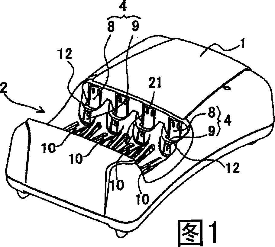
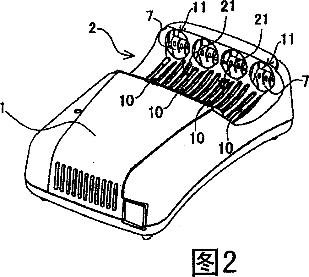
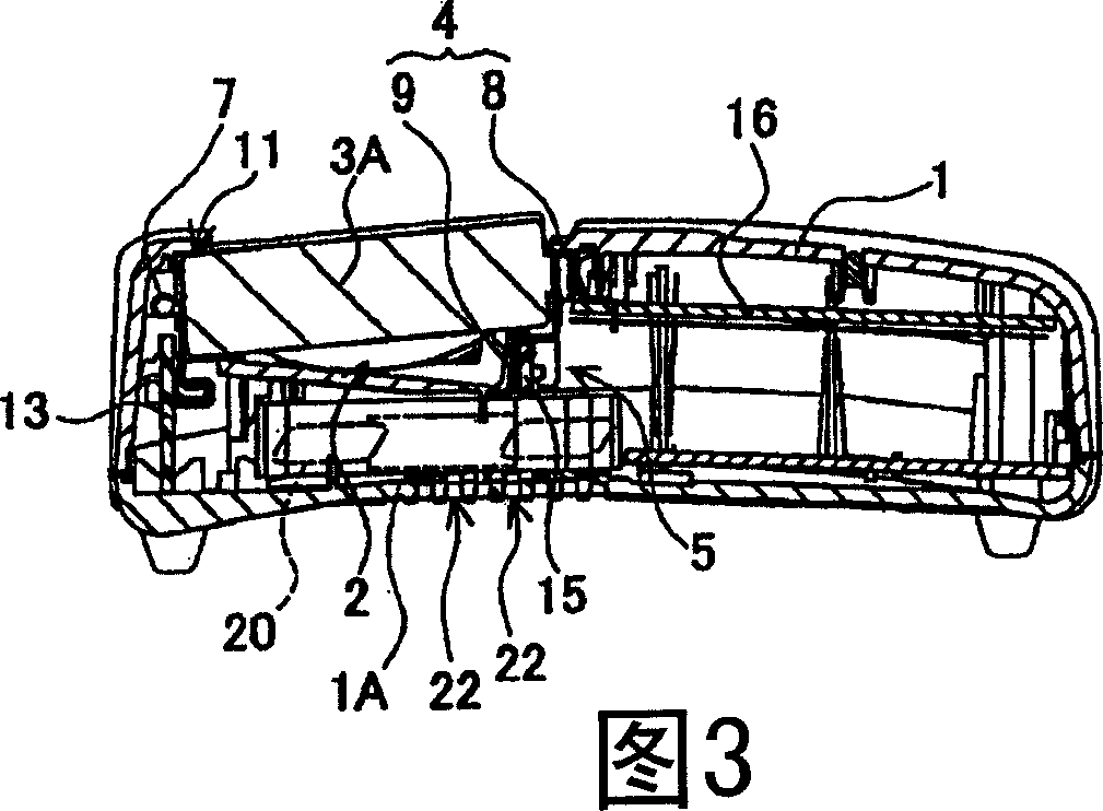
[0064] Hereinafter, embodiments of the present invention will be described with reference to the drawings. However, the embodiments shown below are examples of chargers for embodying the technical idea of ​​the present invention, and the present invention does not specify the chargers as follows. Also, the members shown in the claims are not necessarily specified as the members of the embodiment. In addition, the size, positional relationship, and the like of members shown in the drawings are sometimes exaggerated for the sake of clarity. In addition, in the following description, the same names and reference symbols indicate the same or homogeneous members, and detailed descriptions are appropriately omitted. Furthermore, each element constituting the present invention can also be configured in the form of a plurality of elements with the same member, and a plurality of elements can be used by one member, and vice versa can also be realized by sharing the function of one mem...


PUM


Abstract

The present invention provides a charger capable of accurately detecting the battery temperature of a secondary battery with a simple configuration. The charger of the present invention comprises: a casing (1) having a battery mounting portion (2) for detachably mounting a secondary battery (3) to be charged; a charging circuit built in the casing (1) ), used to charge the secondary battery (3) installed in the battery installation part (2); the first charging terminal (7), which is electrically connected to the charging circuit, is used to connect with the battery installation part ( 2) Any one of the positive and negative electrodes of the installed secondary battery (3) is in contact with and charged; and the second charging terminal (4) is different in polarity from the first charging terminal (7) connected to the charging circuit . The first charging terminal (7) is bent so as to fold back a metal plate to form a sandwich portion (7E) facing the metal plate, and a temperature sensor (14) is disposed on the sandwich portion (7E). A temperature sensor (14) disposed at the clamping portion (7E) detects the battery temperature via a metal plate of a first charging terminal (7) in contact with an electrode of the secondary battery (3).

Description

technical field [0001] The present invention relates to a charger for charging while detecting the temperature of a battery to be charged. Background technique [0002] A charger for charging a secondary battery such as AA battery or AA battery while detecting the temperature of the battery has been developed. The charger performs charging while detecting the temperature of the battery. This is because the performance of the battery decreases when charging is performed while the temperature of the battery is abnormally high. The temperature of the battery rises while charging. In particular, the temperature of the battery will rise rapidly when it is close to being fully charged. An abnormal temperature rise of the battery will cause deterioration of battery characteristics. In order to prevent deterioration of battery performance, a charger equipped with a temperature sensor for detecting the temperature of the battery has been developed (see Patent Documents 1 and 2). ...

Claims


Application Information

Patent Timeline
Patent Type & Authority Applications(China)
IPC IPC(8): H02J7/00H01M10/48G01R31/36H01M10/44H01M10/46H01M10/60H01M10/613H01M10/633H01M10/6556H01M10/6563
CPCH02J7/0045
Inventor 萨摩荣治
Owner SANYO ELECTRIC CO LTD
Why Eureka
Try Eureka