Heat radiating system and method

A technology of a heat dissipation system and a heat dissipation method, which is applied in cooling/ventilation/heating renovation, instrument cooling, instrument and other directions, can solve the problems of reliability of heat dissipation effect and maintenance of heat dissipation fins 12, etc., to prevent accumulation in heat sources, The effect of reducing dust and keeping clean

Inactive Publication Date: 2007-04-04
DELTA ELECTRONICS INC
View PDF0 Cites 10 Cited by
  • Summary
  • Abstract
  • Description
  • Claims
  • Application Information

AI Technical Summary

Problems solved by technology

However, above-mentioned such existing method basically protects the generation source (ie fan 13) of the airflow, rather than protecting the heat dissipation fins 14 or the heat source 11 as the heat dissipation body
The dust in the air will still accumulate on the cooling fins 12 or the heat source 11, which has no effect on the reliability of the cooling effect and the maintenance of the cooling fins 12.

Method used


Image

  • Heat radiating system and method
  • Heat radiating system and method
  • Heat radiating system and method

Examples


Embodiment Construction

[0018] The heat dissipation system and the heat dissipation method thereof according to preferred embodiments of the present invention will be described below with reference to related drawings.

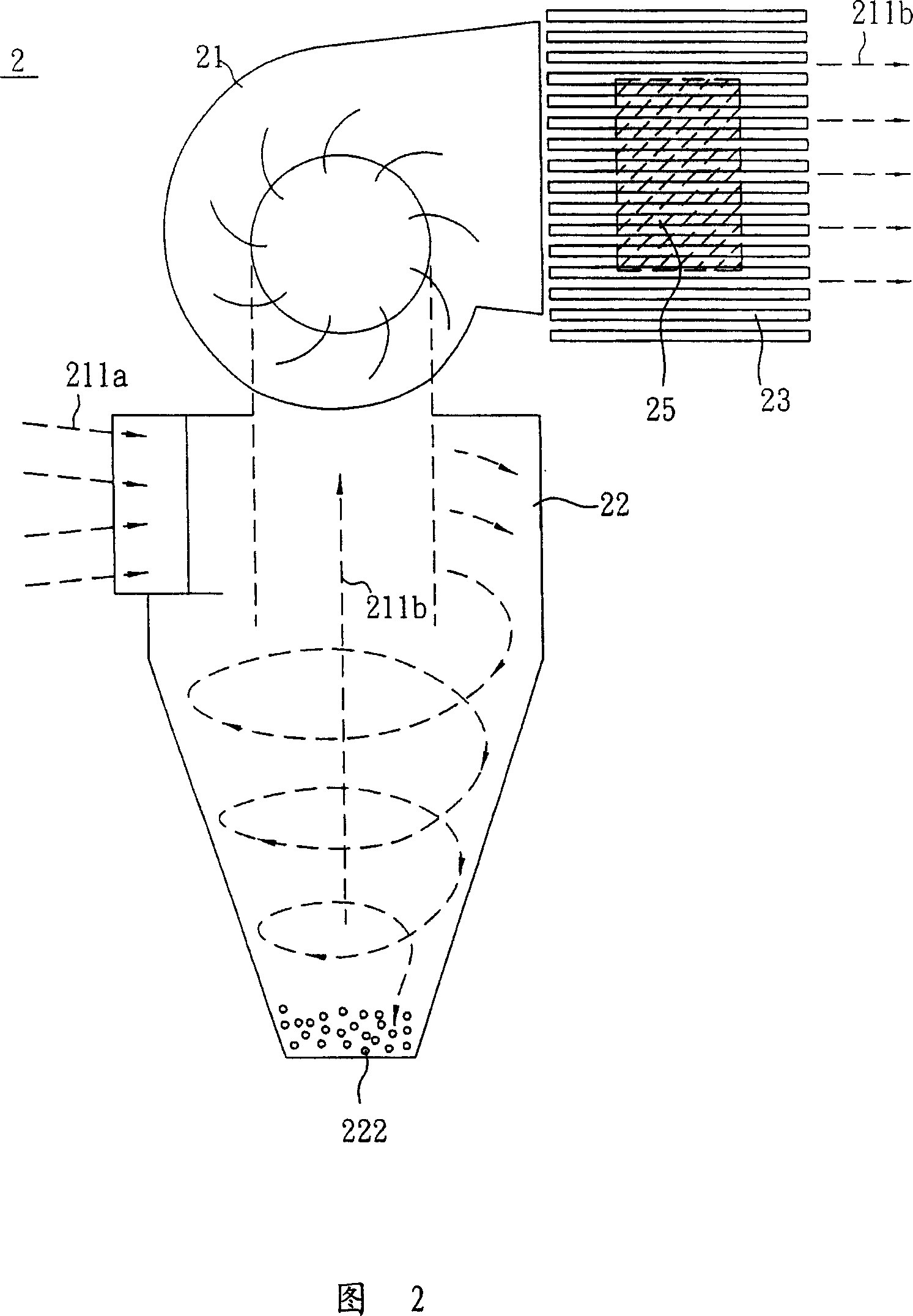
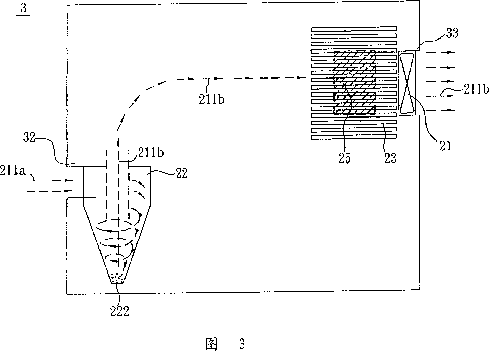
[0019] As shown in FIG. 2 , it is a schematic diagram of a heat dissipation system according to a preferred embodiment of the present invention. The heat dissipation system 2 is applied to a heat source 25 , and the heat dissipation system 2 includes a fan 21 , a dust separator 22 and a heat dissipation fin 23 .

[0020] The fan 21 is an axial fan or a centrifugal fan. When the fan 21 rotates, air is collected from the outside of the heat dissipation system 2 to generate an airflow 211a, and the airflow 211a flows into the dust separation device 22 immediately. Under the action of centrifugal force and gravity, The dust 222 entrained in the airflow 211a will be settled to the bottom of the dust separating device 22, while the separated clean airflow 211b directly enters the fan 21, a...


PUM


Abstract

The invention is used in a thermal source and comprises a fan and a dust separating device. The fan is used to generate an air flow from outside; the air flow is blown into the dust separating device to separate the dust from the air flow; after dust separation, the air flow takes the heat from thermal source.

Description

technical field [0001] The invention relates to a heat dissipation system, in particular to a heat dissipation system of an electronic device. Background technique [0002] As the processing speed of electronic devices is getting faster and faster, resulting in an increase in the heat generated during work, if the heat is not properly handled, it will cause a reduction in the processing speed of electronic devices, and even affect the life of electronic devices in severe cases. Therefore, electronic Heat dissipation fins or fans are often installed in the device to help the electronic device dissipate heat. [0003] Since the influence of dust on cooling fins or heat sources has always been regarded as an unavoidable problem in design, designers regard dust as an unpredictable item, and purely reduce the thermal resistance of cooling fins to ensure the design safety factor. But in fact, the accumulation of dust in the air on fins or heat sources will not only affect the the...

Claims


Application Information

Patent Timeline
Patent Type & Authority Applications(China)
IPC IPC(8): H05K7/20G06F1/20G12B15/04
Inventor 叶东昌林永彬
Owner DELTA ELECTRONICS INC
Why Eureka
Try Eureka