
Presser foot device of seam plainer

A technology of presser foot device and lockstitch sewing machine, which is applied in the direction of sewing machine components, cloth pressing mechanism, sewing equipment, etc. It can solve the problems of reduced work efficiency, uneven feeding, and staggered upper and lower layer materials, so as to improve work efficiency and feed materials. Smooth, avoiding the effect of misalignment

Inactive Publication Date: 2007-04-11
FEIYUE
View PDF0 Cites 9 Cited by
  • Summary
  • Abstract
  • Description
  • Claims
  • Application Information

AI Technical Summary

Problems solved by technology

The upper material in contact with the bottom surface of the presser foot is fed too slowly due to the small friction force, and the upper and lower materials have misalignment and uneven feeding, especially when sewing thin materials, resulting in low yield and high production cost. , reduced work efficiency

Method used


Image

  • Presser foot device of seam plainer
  • Presser foot device of seam plainer
  • Presser foot device of seam plainer

Examples


Embodiment Construction

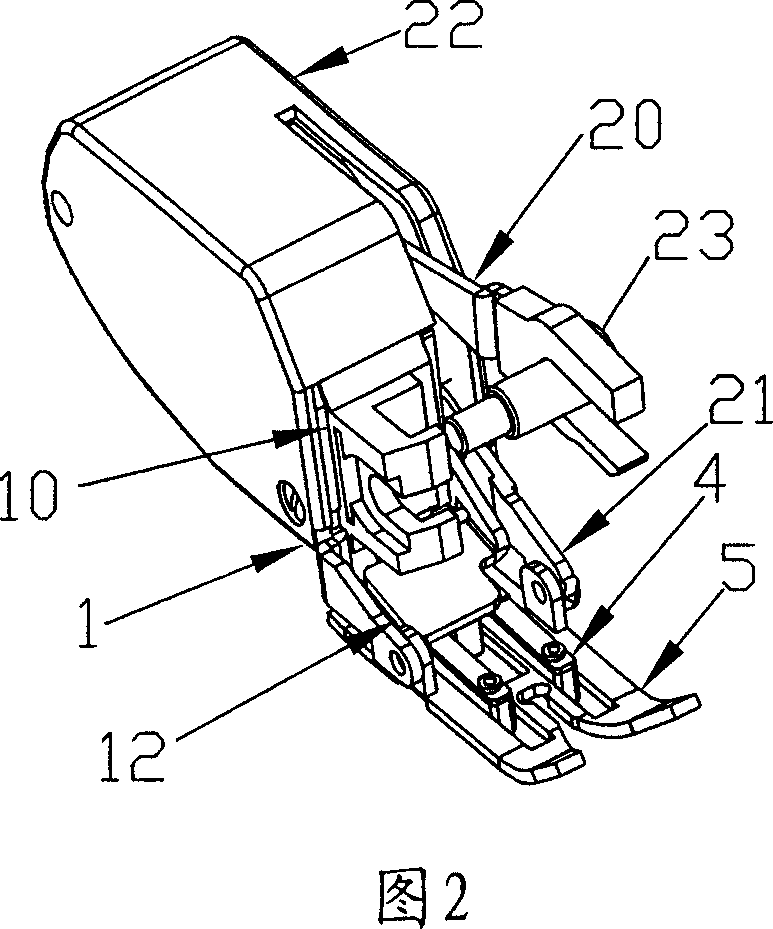
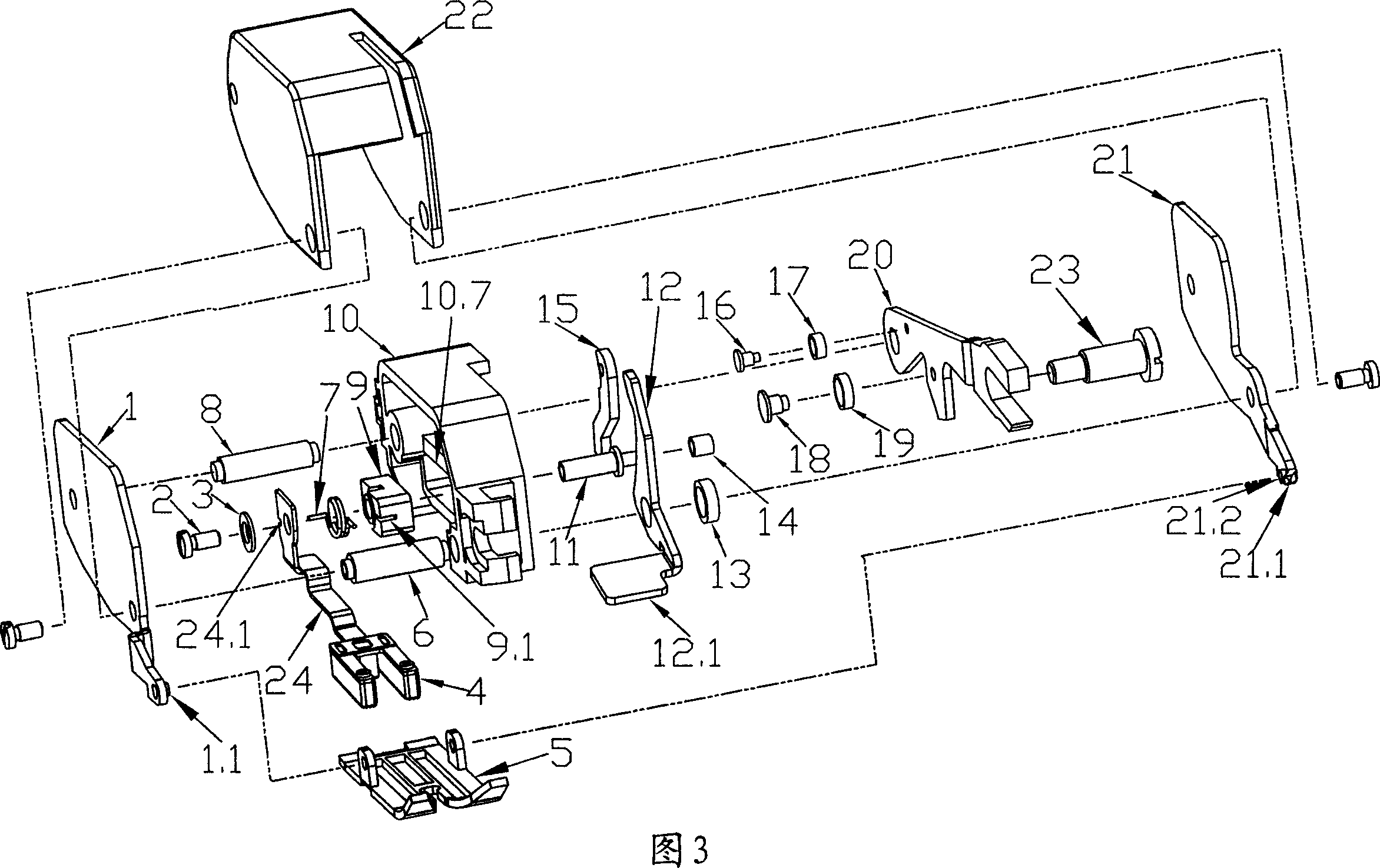
[0019] Referring to Fig. 2, the present invention is encapsulated by a case 22, and the fork at the end of the driving rod 20 passing through the opening groove on the case 22 is movably matched with the needle clamp screw 23, and the connecting part of the skeleton 10 is passed through the front side of the case 22, which is convenient Fixed with the pressure rod. The left and right splints 1, 21 are installed in the casing 22, and the front end is respectively shaped on a protruding shaft, and the protruding shaft is axially connected with the presser foot base plate 5 rear ends. The feeding block 4 is movably installed in the groove of the presser foot base plate 5, and is driven by a transmission mechanism to run back and forth in the groove; the pressing plate 12 is arranged on the top of the feeding block 4.

[0020] With reference to Fig. 3, the feeding block transmission mechanism of the present invention is made up of driving rod 20, driving lever 15, pressing plate 1...


PUM


Abstract

The presser foot device for seam plainer is installed to the ends of the skeleton on the bottom of the press stem and has right and left clamp plates, presser foot back plate connected to the shaft stretched from the clamp plates, driving rod fixed inside the skeleton with front fork fitted with the needle clamp screw movably, and feeding block driven by the transmission mechanism to reciprocate inside the longitudinal slot in the presser foot back plate. During sewing, the feeding block has its teeth matching the feeding teeth to clamp the material to feed backward. The present invention can ensure smooth material feeding without slipping between the upper and the lower material layers, high sewing quality and high work efficiency.

Description

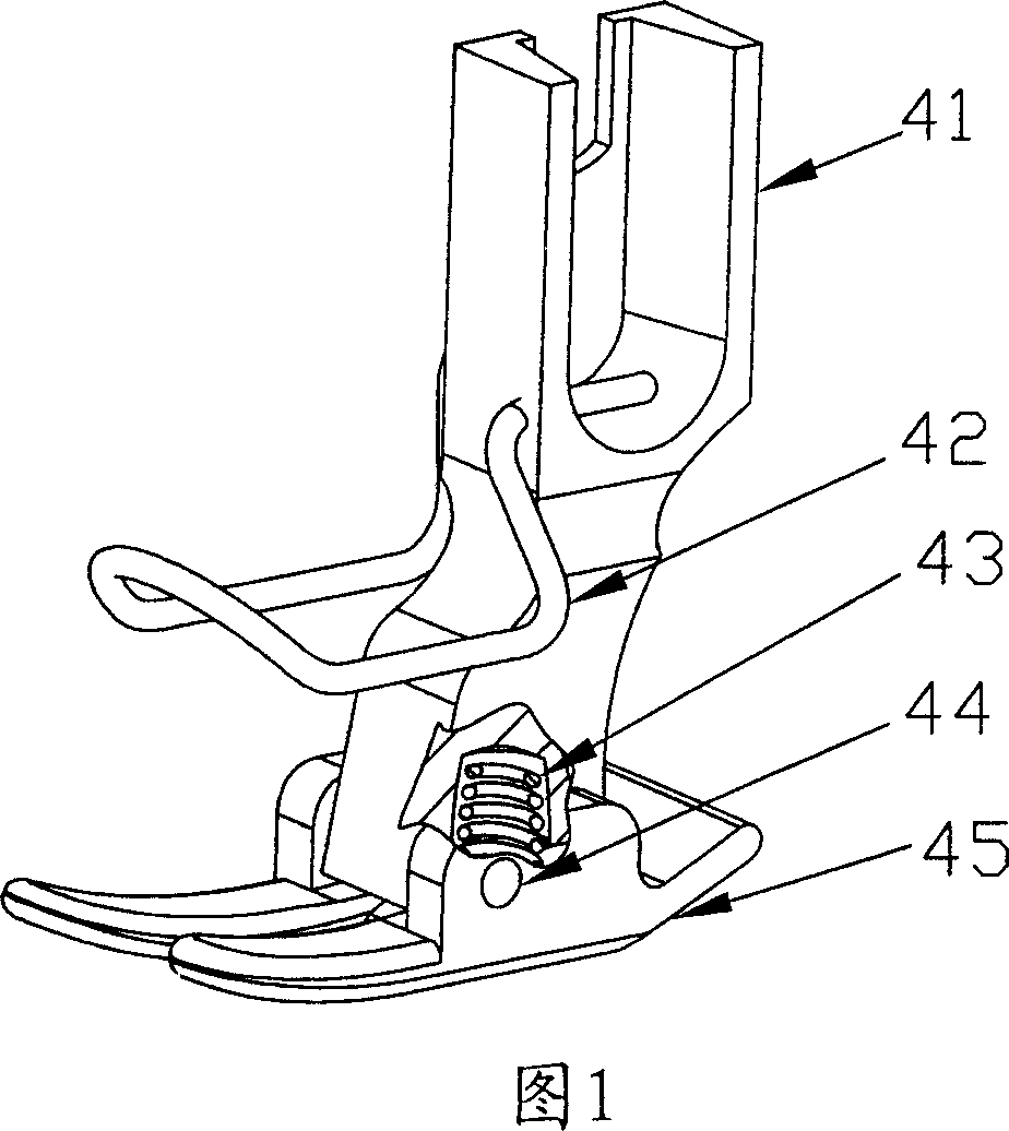
Technical field: [0001] The invention relates to a component structure of a sewing machine, in particular to a presser foot device of a lockstitch sewing machine. Background technique: [0002] The presser foot device of the existing lockstitch sewing machine is shown in Figure 1, the presser foot pin 44 movably connects the presser foot handle 41 and the presser foot bottom plate 45, and the presser foot spring 43 is arranged in the presser foot handle 41 and conflicts with the presser foot bottom plate 45 , Presser foot needle guard frame 42 is installed on the presser foot handle 41. During work, the presser foot device moves downward with the pressing of the pressure rod, so that the presser foot base plate 45 and the needle plate work together to clamp the material. The friction force generated between the materials is relatively small, while the friction force between the feeding teeth on the needle plate and the materials is relatively large, which will make the fric...

Claims


Application Information

Patent Timeline
IPC IPC(8): D05B29/06
Inventor 张显顺阮炳辉宁德民
Owner FEIYUE
Learn More