Automatic needle inserting machine

A pin insertion machine and automatic technology, applied in the field of pin insertion of stamping parts, can solve the problems of unguaranteed product quality, high labor cost, low efficiency, etc., to avoid empty insertion or malfunction, save time, and improve production efficiency Effect

Active Publication Date: 2007-04-11
BELTON ELECTRONICS SHENZHEN
View PDF0 Cites 28 Cited by
  • Summary
  • Abstract
  • Description
  • Claims
  • Application Information

AI Technical Summary

Problems solved by technology

However, this manual method is inefficient, and the labor cost is high, and the product quality cannot be guaranteed.
With the improvement of automation technology, it is now necessary to use the automatic needle insertion method. Although the current design of the automatic needle insertion machine is much more efficient than the previous manual needle insertion, this automatic needle insertion machine only has one station. , and simply arrange the copper needles by vibrating on the vibrating plate, and then send the copper needles to the fixture working position in order to complete the needle insertion process with the needle groove. It is still necessary to manually determine the placement of the parts, and this placement will exist. The problem of whether the parts are in the correct working position and whether the needle is placed in the correct pinhole position, the whole working process is unreliable, the working efficiency still cannot keep up with the requirements of modern production, and there is no safety device in the working process to ensure the safety of operators

Method used


Image

  • Automatic needle inserting machine
  • Automatic needle inserting machine
  • Automatic needle inserting machine

Examples


Embodiment Construction

[0036] The present invention will be explained in detail below in conjunction with the accompanying drawings and specific embodiments.

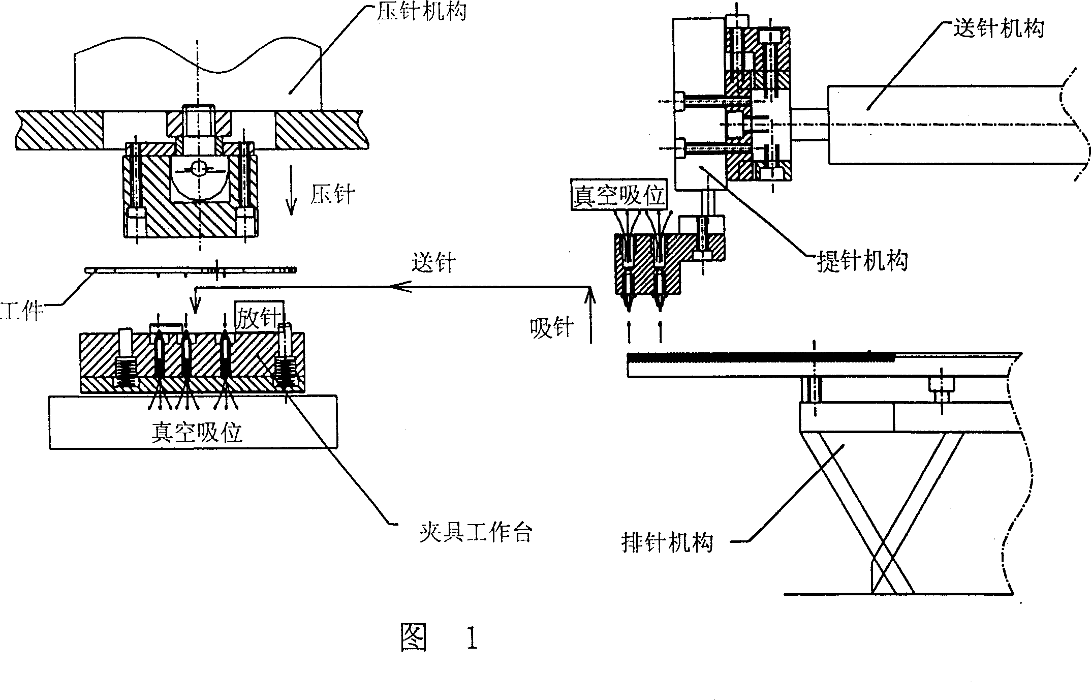
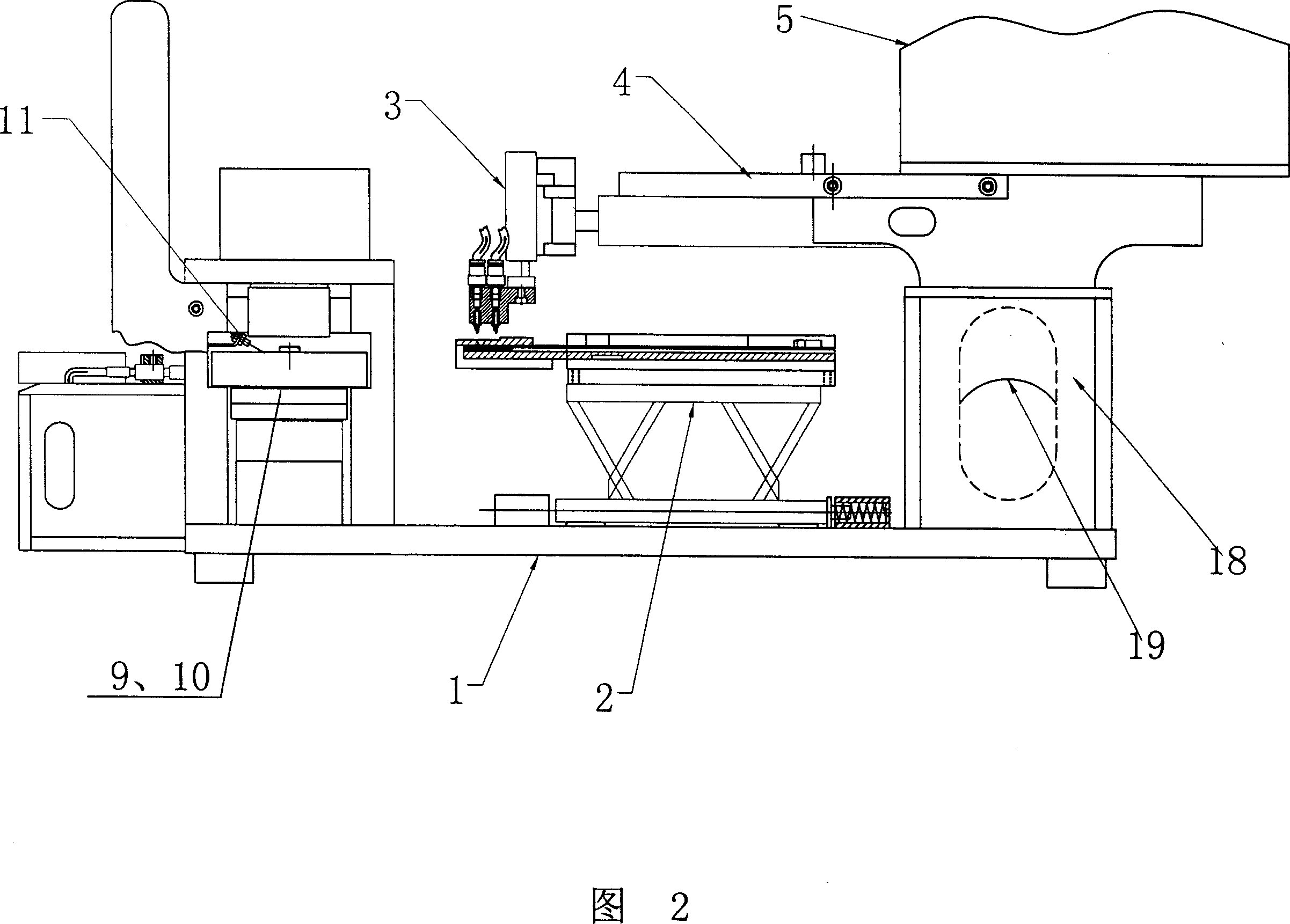
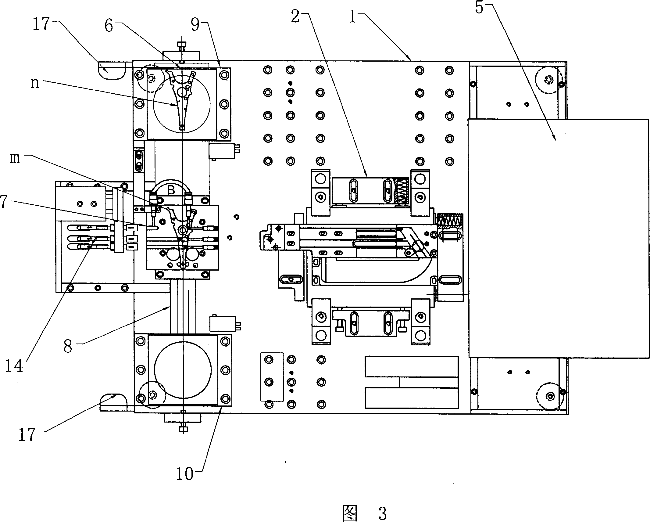
[0037] First, the working principle of the present invention will be described with respect to FIG. 1 . As shown in Figure 1, the present invention includes a base and an electric control box, the base is the carrier of the entire pin insertion machine, and other components are installed on the base, and the electric control box can accommodate the entire control system, including various start switches , control components, etc., on the bearing base, there is a fixture workbench, and the plug-in can be fixed on the fixture workbench. For example, the hard disk drive bracket that needs to be inserted or other parts that need to be processed can be placed on the workbench. It is fixed on the station, and the needle row mechanism is set behind the fixture table, including a vibrator and a suspended needle lifting cylinder. The vibrator is provi...


PUM


Abstract

This invention relates to an automatic pin-plug machine including an integral bearing basis and an electric control box loading a control device characterizing that the loading basis is set with a working stand, a pin-arranging device, a pin-feeding unit and a pressing unit, in which, a spare part test fiber head and an inducing switch are connected on the clamp working stand, a vacuum butt-joint piston is set at the front position of the working stand and connected on the vacuum generator, a vacuum absorption position is set at the bottom of the clamp base and connected with the vacuum butt joint piston by a vacuum cupule, which breaks through the traditional pin-plug way.

Description

【Technical field】 [0001] The invention relates to the field of pin insertion of stamping parts, in particular to an automatic pin insertion machine applied to similar structures such as hard disk drive brackets. 【Background technique】 [0002] With the rapid development of industrial society, the categories of electronic products are gradually increasing. In more and more electronic products, it is often necessary to insert other small needle parts on the parts. For example, the hard disk drive bracket in the computer needs to insert copper needles to fix the flexible cable sheet and the ground connection. Take this hard disk drive bracket as an example, the earliest way at first is to manually insert the needle at the pinhole position of the hard disk drive bracket, and then put the hard disk drive bracket after the needle is placed on a small punch to press the needle tightly. However, this manual method is inefficient, and the labor cost is high, and the product quality ...

Claims


Application Information

Patent Timeline
Patent Type & Authority Applications(China)
IPC IPC(8): G11B33/00B23P19/00
Inventor 刘志明曹桐鸣陈珏然
Owner BELTON ELECTRONICS SHENZHEN
Why Eureka
Try Eureka