
Stand for irradiation device

A radiotherapy and gantry technology, applied in radiotherapy, treatment, instruments for radiological diagnosis, etc., can solve the problems of reducing assembly space, obstacles, etc., and achieve the effect of low design cost

Inactive Publication Date: 2007-04-18
SIEMENS AG
View PDF1 Cites 8 Cited by
  • Summary
  • Abstract
  • Description
  • Claims
  • Application Information

AI Technical Summary

Problems solved by technology

On the other hand, the respective instrument parts are located in the same beam range and thus interfere with each other
As a result, the available assembly space is reduced and the components have to be space-saving or coordinated with one another and integrated into the diagnostic and / or therapeutic device

Method used


Image

  • Stand for irradiation device
  • Stand for irradiation device
  • Stand for irradiation device

Examples


Embodiment Construction

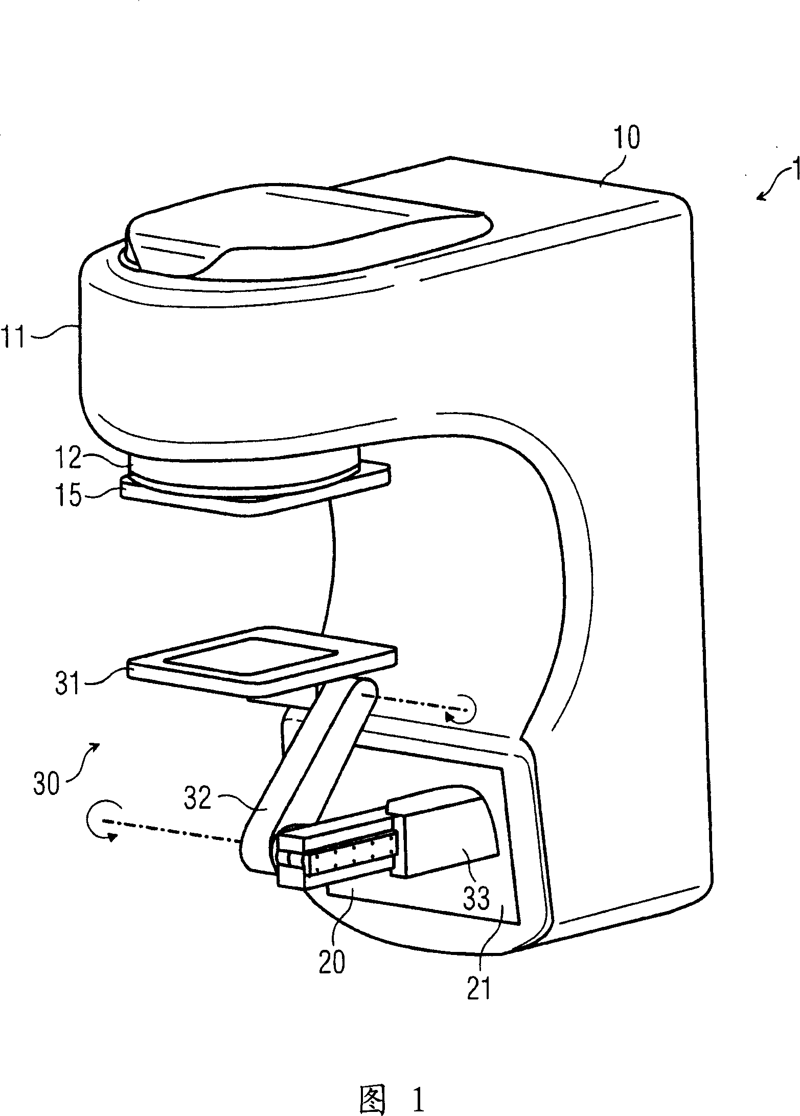
[0029] FIG. 1 schematically shows a perspective view of a radiotherapy system 1 . The radiotherapy device comprises a gantry 10 mounted rotatably about a horizontal axis and carrying some important functional parts of the radiotherapy device 1 .

[0030] The gantry 10 has a radiation head 11 from which the therapeutic radiation emerges, specifically in the downward direction in this figure. The patient to be treated with radiation (not shown) positions the body part to be treated with radiation below the radiation head 11 on a patient positioning device (also not shown). A beam shaper 12 is provided on the radiation head 11 , which serves in particular to shape the beam profile. For this purpose, the shaper may contain a focusing device, one or more orifice plates and one or more collimation tubes.

[0031]Arranged below the beam shaper 12 is a kV detector 15 with which x-rays in the kV energy range can be detected. On the one hand, the kV detector 15 can detect the contour...


PUM


Abstract

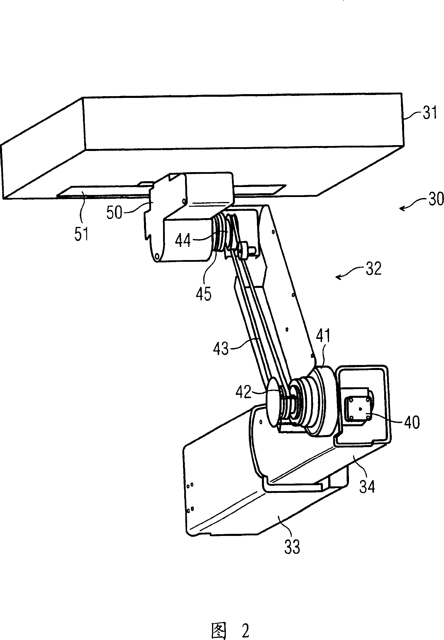
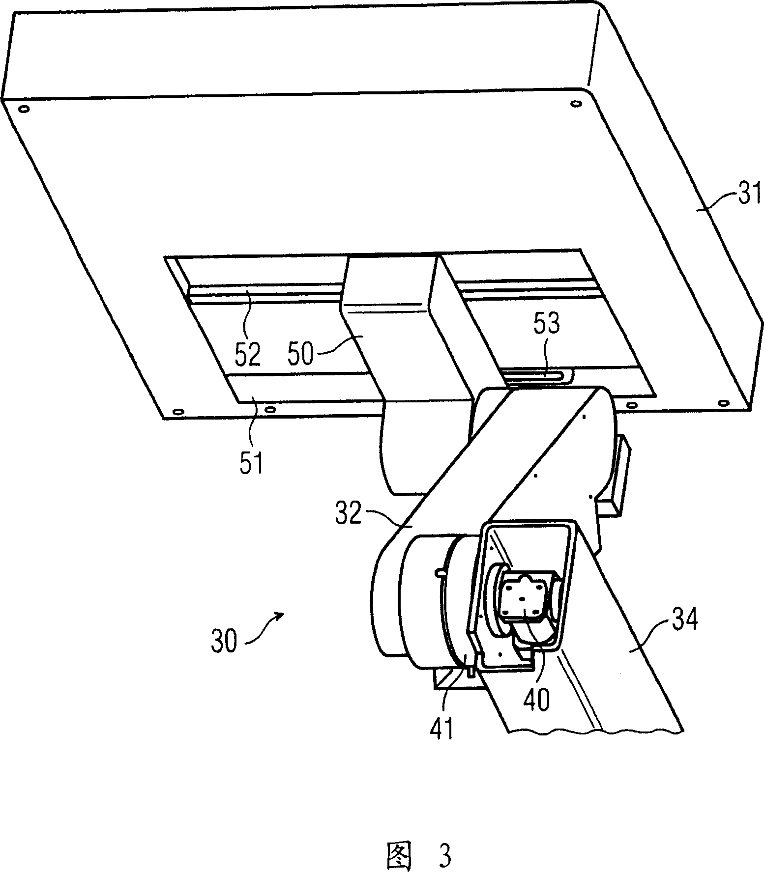
The invention relates to a bracket of a radiotherapy apparatus. According to an advantageous embodiment, the support (30) comprises a longitudinally adjustable elongated support arm, a lever arm (32) rotatably supported in the support arm about a first axis perpendicular to the support arm, and in the support arm A flat detection element rotatable in the lever arm (32) about a second axis parallel to the first axis, the detection element being oriented substantially parallel to the support arm, wherein the detection element remains with the support when the lever arm (32) is rotated The arms are oriented in parallel and a motor (40) drives the lever arm (32) in rotation. The rotation of the lever arm (32) is transmitted through the first transmission device (41) connected with the electric motor (40), and the rotation of the detection element is reversed through the first transmission device (41) connected with the same electric motor (40). The second transmission device (45) of the transmission is used for transmission. Such an arrangement with a single electric motor (40) and two gears (41, 45) working in opposite directions can be realized with very precise positioning and at the same time requiring only a small construction volume or space.

Description

technical field [0001] The invention relates to a bracket of a radiotherapy apparatus. Background technique [0002] Radiation therapy machines are used in medical treatments such as radiation to treat diseased tissue, such as tumor tissue. Types of radiation suitable for this treatment include, for example, high-energy X-rays in the megavolt (MV) range, light particle radiation such as electrons or positrons or protons, heavy particle radiation such as oxygen ions or carbon ions. Living tissue is altered by radiation treatment: connections may be disrupted or atoms may be ionized. These changes can cause damage or kill tissue. While it is this effect that is consciously directed at tumor or diseased tissue, on the contrary, it should be avoided as much as possible on healthy tissue. Therefore, by treating only the tumor tissue with radiation as targeted as possible, the radiation dose administered in the tumor tissue is increased on the one hand and the radiation dose ad...

Claims


Application Information

Patent Timeline
Patent Type & Authority Applications(China)
IPC IPC(8): A61N5/10A61N5/00F16M11/00
CPCA61N2005/1054A61N5/1049A61B6/00F16M11/18F16M11/38
Inventor 弗朗兹·法德勒
Owner SIEMENS AG
Learn More