Active vibration-damping device for cutting equipment, and control method thereof
An active vibration reduction and equipment technology, applied in the direction of automatic control devices, feeding devices, metal processing equipment, etc., can solve the problems of unsatisfactory precision and control precision, and achieve the effect of small working stress and improved processing accuracy
- Summary
- Abstract
- Description
- Claims
- Application Information
AI Technical Summary
Problems solved by technology
Method used
Image
Examples
Embodiment 1
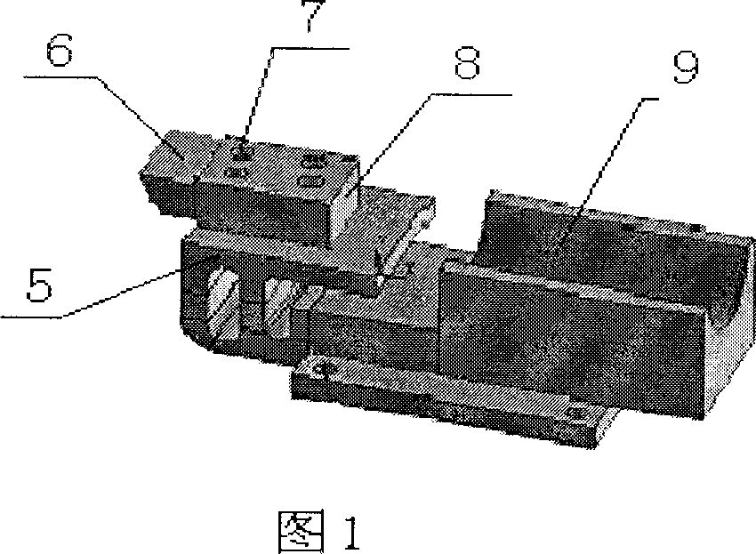
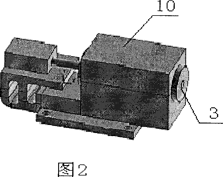
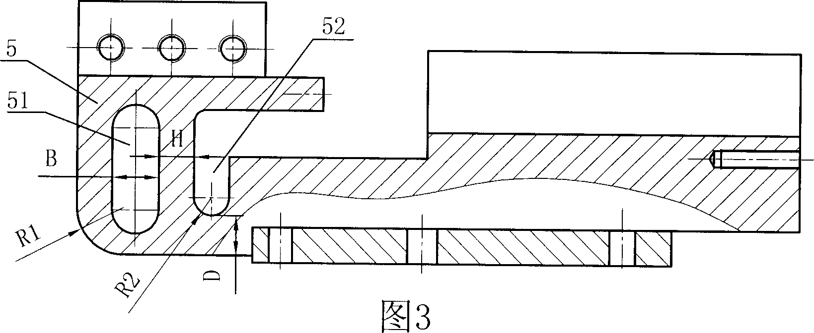
[0022] Embodiment 1: As shown in the figure, an active damping device for turning equipment includes a high-precision vibration sensor 1, a controller 2, a giant magnetostrictive actuator (GMA) 3 and a tool holder 4, and the head of the tool holder 4 A tool holder fixing seat 5 is provided, and the tool holder 8 is fixedly arranged on the tool holder fixing seat 5. The tool 6 and the tool holder 8 are fixed with nuts 7. The tail of the tool holder 4 is provided with a circular groove 9, and the giant magnetostrictive actuator 3 Set in the cavity formed by the round groove 9 and the semi-cylindrical groove cover 10, the toolholder holder 5 is provided with a vibration-damping groove 52 and a weight-reducing hole 51 parallel to the vibration-damping groove 52, and the toolholder holder 5 A radius R1=20mm is formed between the front end surface and the lower end surface of the tool holder holder 5. The outer fillet of the radius R1=20mm, the bottom of the damping groove 52 is a se...
Embodiment 2
[0030] Embodiment 2: Others are the same as Embodiment 1, the difference is that a radius R1=18mm is formed between the front end surface of the toolholder holder 5 and the lower end surface of the toolholder holder 5, and the bottom of the damping groove 52 Be the semicircular groove of radius R2=7mm, the distance D=18mm between the bottom end of damping groove 52 and the lower end surface of tool holder holder 5, the width B=14mm of weight reducing hole 51, weight reducing hole 51 and vibration damping The wall thickness H between the grooves 52 is 15 mm.
Embodiment 3
[0031] Embodiment 3: Others are the same as Embodiment 1, the difference is that a radius R1=22mm is formed between the front end surface of the toolholder holder 5 and the lower end surface of the toolholder holder 5, and the bottom of the damping groove 52 Be the semicircular groove of radius R2=8mm, the distance D=22mm between the bottom end of damping groove 52 and the lower end surface of tool holder holder 5, the width B=16mm of weight reducing hole 51, weight reducing hole 51 and vibration damping The wall thickness H between the grooves 52 is 13 mm.
PUM
| Property | Measurement | Unit |
|---|---|---|
| Radius | aaaaa | aaaaa |
| Radius | aaaaa | aaaaa |
Abstract
Description
Claims
Application Information
 - R&D
- Intellectual Property
- Life Sciences
- Materials
- Tech Scout
- Unparalleled Data Quality
- Higher Quality Content
- 60% Fewer Hallucinations
Browse by: Latest US Patents, China's latest patents, Technical Efficacy Thesaurus, Application Domain, Technology Topic, Popular Technical Reports.
© 2025 PatSnap. All rights reserved.Legal|Privacy policy|Modern Slavery Act Transparency Statement|Sitemap|About US| Contact US: help@patsnap.com


