Differential material feeding device of sewing machine
A feeding device and sewing machine technology, applied in the direction of sewing machine control devices, sewing machine components, sewing equipment, etc., can solve the problems affecting the normal adjustment of differential feed, large friction between forks and sliding parts, and wear of forks and sliding parts and other problems, to achieve the effect of small strength, simple and compact structure, and stable transmission
- Summary
- Abstract
- Description
- Claims
- Application Information
AI Technical Summary
Problems solved by technology
Method used
Image

Examples
Embodiment 1
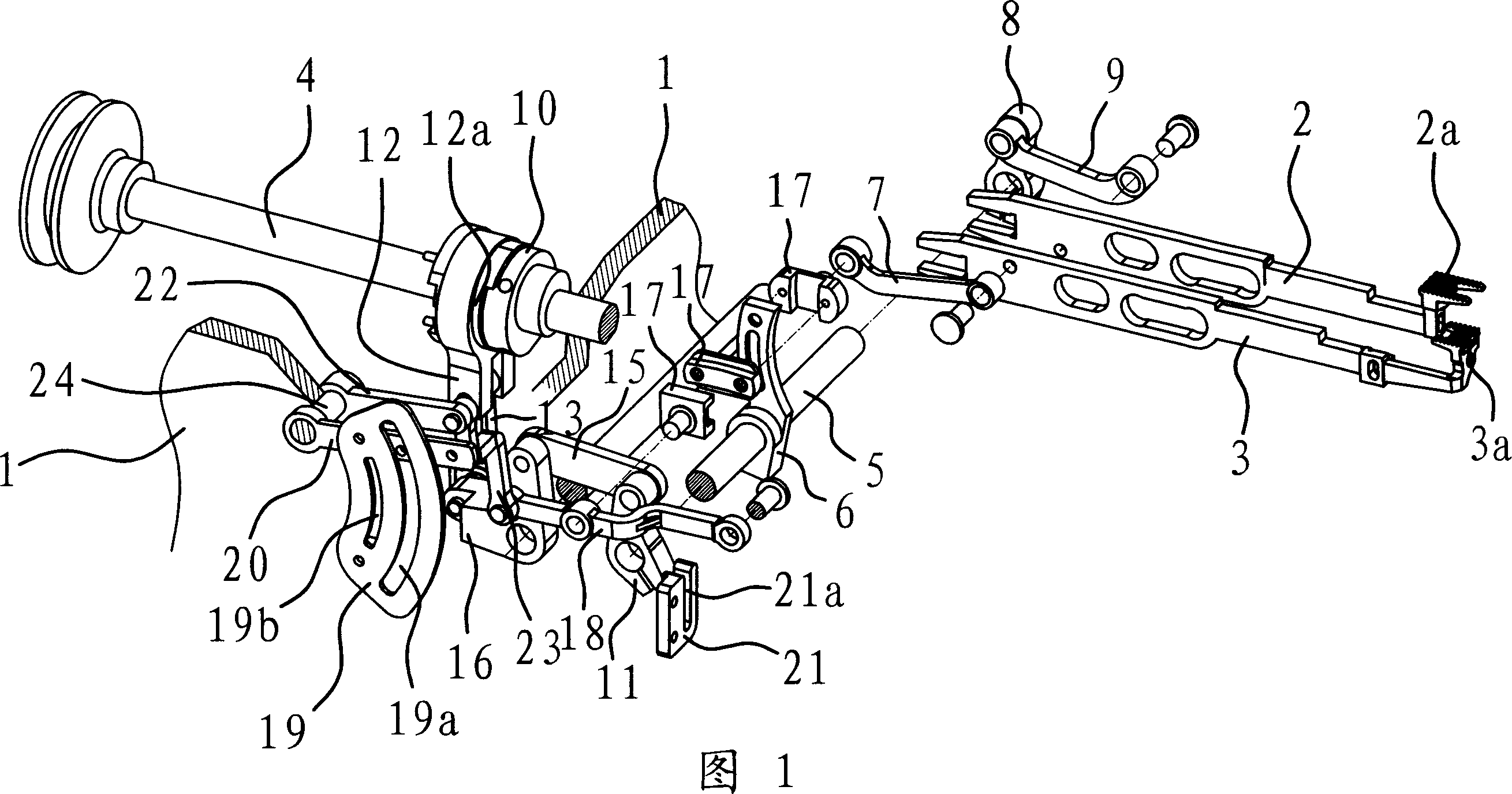
[0036] As shown in Figure 1, the differential feeding device of this sewing machine is set at the frame 1 of the sewing machine, through which the differential feeding can be realized so that the collar of the T-shirt, the overlock of the cuff of the clothes, and the seam of the hem of the long cuff Class parts are sewed.
[0037] The differential feeding device of the sewing machine includes a power main shaft 4, a transmission shaft 5, a feeding tooth 2a, a differential tooth 3a and the like. In this embodiment, the power main shaft 4 is fixedly connected with a pulley, and the motor drives the power main shaft 4 to rotate through the belt. The feed dog 2a is fixedly connected to the feed dog frame 2, the differential tooth 3a is fixedly connected to the differential dog frame 3, and both the feed dog frame 2 and the differential dog frame 3 are on the frame 1 of the sewing machine.
[0038] The power spindle 4 drives the transmission shaft 5 to rotate through the transmiss...
Embodiment 2
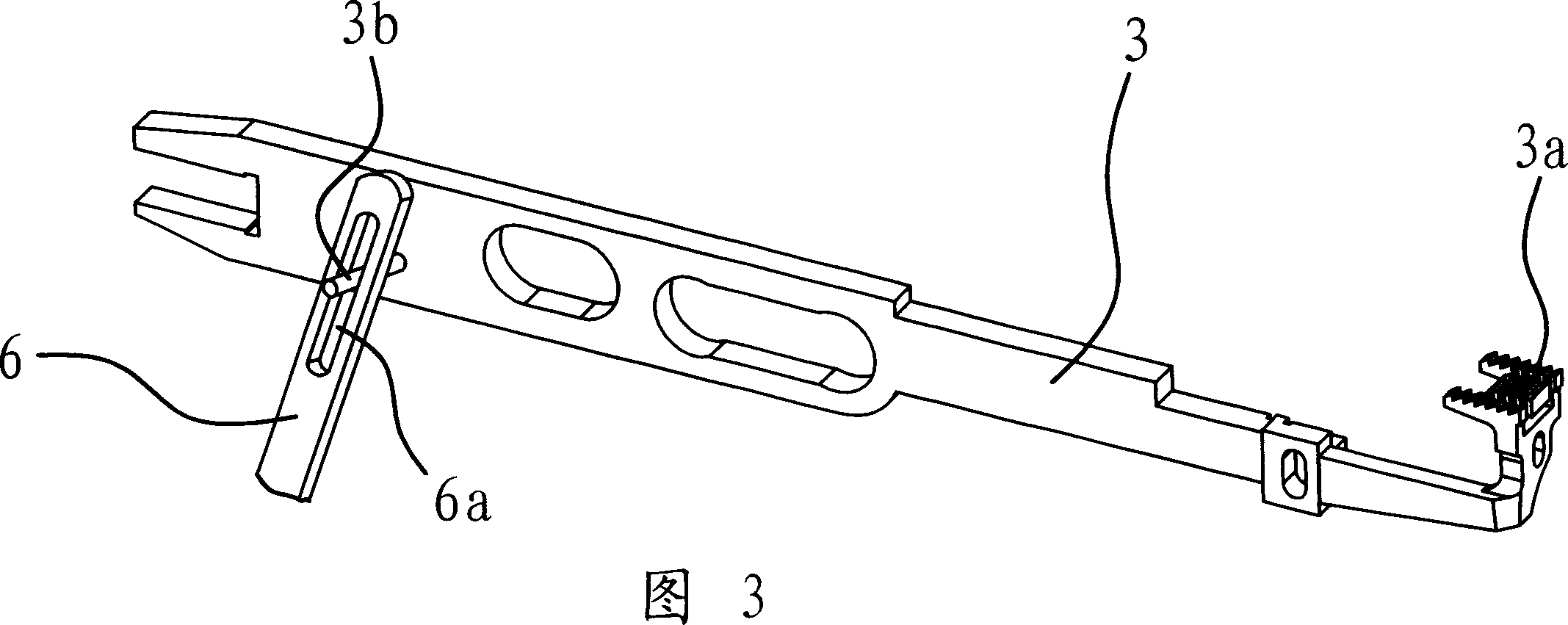
[0051] The mechanism and principle of this embodiment are basically the same as that of Embodiment 1, the difference is that the differential mechanism is a differential handle 6, one end of which is fixedly connected to the transmission shaft 5, and the other end is provided with a bar-shaped hole 6a , the above-mentioned differential tooth frame 3 is provided with a protruding head 3b, and the protruding head 3b is located in the bar-shaped hole 6a, as shown in FIG. 3 .
Embodiment 3
[0053] The mechanism and principle of this embodiment are basically the same as that of Embodiment 1, the difference is that the feeding mechanism is a feeding handle 8, one end of the feeding handle 8 is fixedly connected to the transmission shaft 5, and the other end is provided with a strip hole 8a, the above-mentioned A protruding head 2b is provided on the feeding dog frame 2, and the protruding head 2b is located in the strip-shaped hole 8a, as shown in FIG. 4 .
PUM
 Abstract
Description
Claims
Application Information
 - Generate Ideas
- Intellectual Property
- Life Sciences
- Materials
- Tech Scout
- Unparalleled Data Quality
- Higher Quality Content
- 60% Fewer Hallucinations
Browse by: Latest US Patents, China's latest patents, Technical Efficacy Thesaurus, Application Domain, Technology Topic, Popular Technical Reports.
© 2025 PatSnap. All rights reserved.Legal|Privacy policy|Modern Slavery Act Transparency Statement|Sitemap|About US| Contact US: help@patsnap.com