
Piston for the crosshead engine

A crosshead type engine technology, which is applied to the engine, especially the piston of a two-stroke large diesel engine, can solve the problems of affecting the cooling effect and the cooling of the bottom of the hole, and achieve the effect of improving the cooling effect and high heat exchange

Active Publication Date: 2007-04-18
MAN DIESEL & TURBO FILIAL AF MAN DIESEL & TURBO SE TYSKLAND
View PDF3 Cites 12 Cited by
  • Summary
  • Abstract
  • Description
  • Claims
  • Application Information

AI Technical Summary

Problems solved by technology

A disadvantage in this respect is that during the downward movement of the piston, the coolant is squeezed into the cooling bores and forms a practically fixed fill there, which suppresses the jets emerging from the nozzles and cannot be penetrated by them, This adversely affects the cooling effect
In addition, the nozzles here are not arranged concentrically to the bore axis, but rather are inclined, so that the jets emerging from them impinge on the side walls of the respectively assigned bore, which can affect the cooling of the bore bottom.

Method used


Image

  • Piston for the crosshead engine
  • Piston for the crosshead engine
  • Piston for the crosshead engine

Examples


Embodiment Construction

[0018] The main field of application of the present invention is two-stroke large diesel engines in a crosshead configuration, for example in ship drives and the like. The structure and principle of action of such engines are known per se.

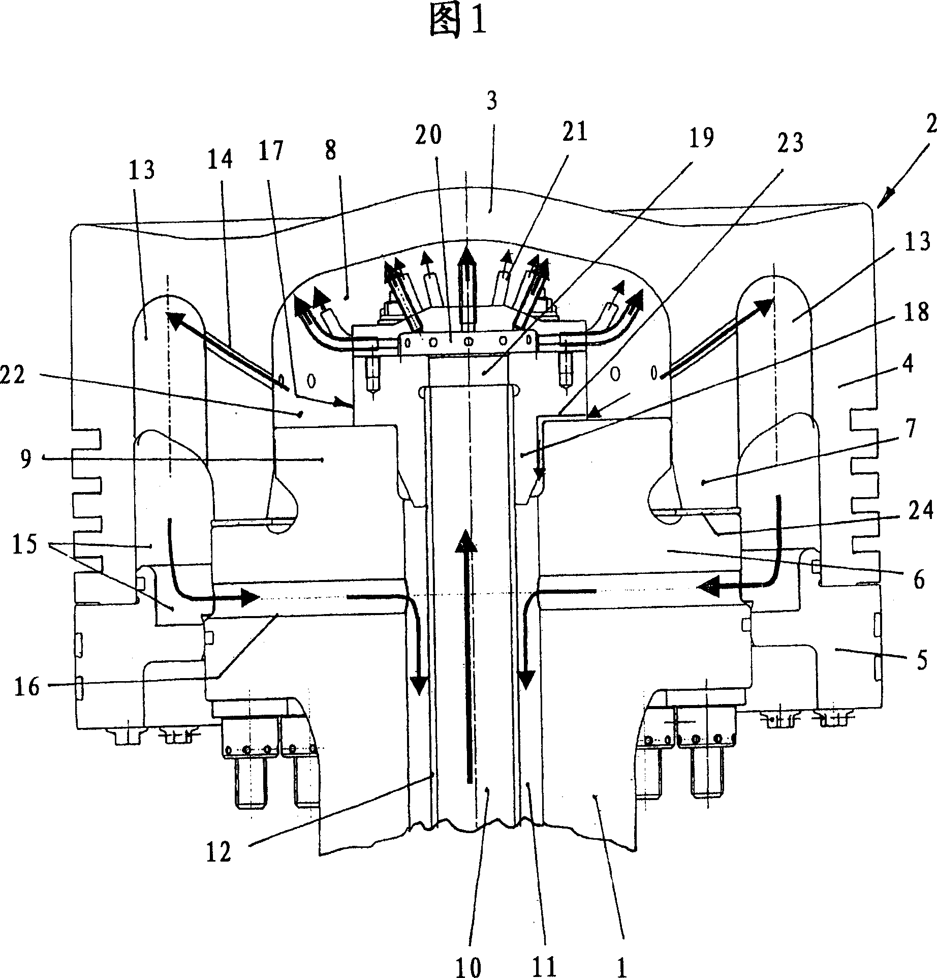
[0019] The piston shown in FIG. 1 is connected via a piston rod 1 to a crosshead, not shown in more detail. The piston comprises a piston upper part 2 with a piston head 3 facing the combustion chamber and a piston skirt 4 surrounding the outer edge accommodating the piston head 3, on which a piston lower part 5 is mounted. The piston upper part 2 is mounted on a flange 6 arranged in the region of the upper end of the piston rod 1 . For this purpose, the surrounding piston skirt 4 is provided with a radially inner annular strip 7 mounted on the flange 6 through the intermediate connection of a seal 24, which together with the piston head 3 delimits a piston upper part 2 as The piston head 3 is equipped with a central cooling chamber 8 . ...


PUM


Abstract

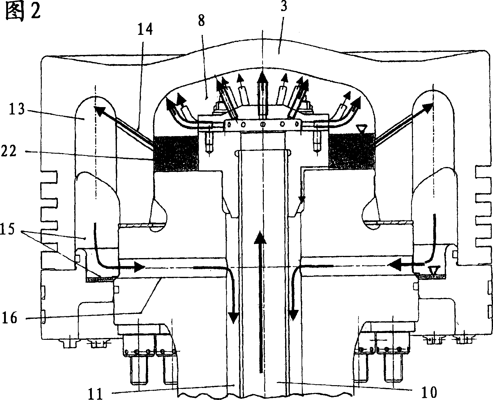
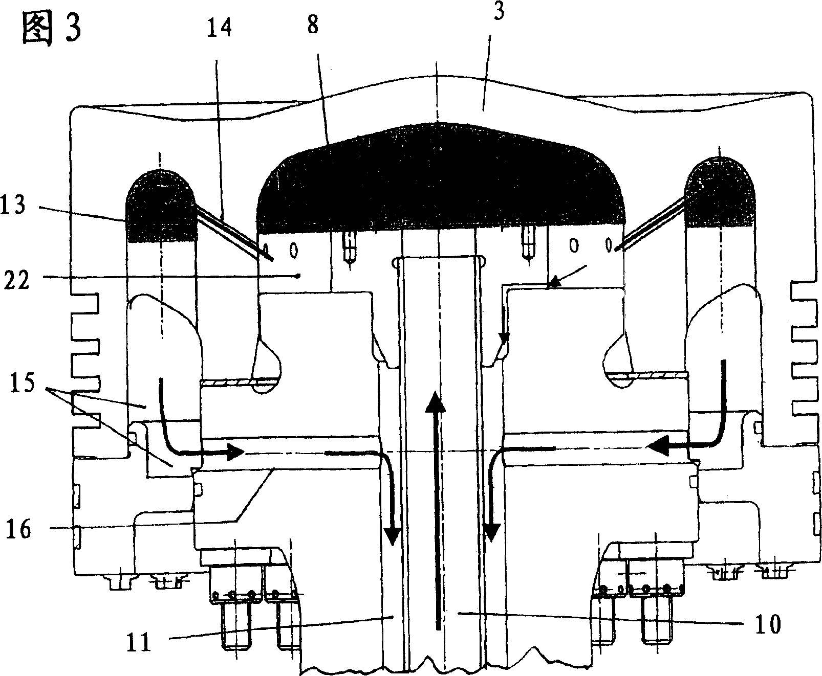
A piston for the crosshead engine, in particular a piston is used for a large two-cycle diesel engine and is provided with a piston upper part (2) mounted to an upper flange (9) of a piston rod (1). The piston upper part is provided with the piston crown (3) connected to a piston skirt (4) annularly surrounding the periphery, and the piston crown covers the central cooling chamber (8). In this chamber (8), coolant can be injected via a supply line (10) arranged inside the piston rod (1), and can be carried away via a return line (11) provided outside in the radial direction of the line (10). Provided is a highly reliably cool a piston crown, in a piston provided with the piston crown having a rising center or with a cooling chamber formed to have an inserting body (17). The inserting body (17) has opposite inner nozzle (21) connecting to the supply pipelines (10) pointing to the piston crown (3) enclosed by an annular cell (22) which is formed into a coolant collecting chamber.

Description

technical field [0001] The invention relates to a piston for a crosshead engine, in particular a two-stroke large diesel engine, comprising a piston upper part mounted in the region of the upper end of the piston rod, the piston upper part having a piston skirt connected to a surrounding The upper piston head covers a central cooling chamber which can be supplied with coolant via a supply line arranged in the piston rod and which can be discharged via a return line arranged radially outside the supply line. Background technique [0002] A device of this type is known from DE 199 62 325 C2. In this known device, a coolant jet emerges from the upper end of a supply line formed by a central bore through a piston rod, which emerges in the central region of the inner side of the piston head. The area is depressed in the center here. This results in a contour of the upper boundary of the cooling chamber that gradually rises radially outward from the center. The coolant impingin...

Claims


Application Information

Patent Timeline
Patent Type & Authority Applications(China)
IPC IPC(8): F02F3/22
CPCF02F3/22F16J1/00F16J1/09
Inventor E·克罗内
Owner MAN DIESEL & TURBO FILIAL AF MAN DIESEL & TURBO SE TYSKLAND
Learn More