Mechanism for the recovery of energy in self-propelled vehicles

An energy recovery device, technology for motor vehicles, applied in the field of new systems, capable of solving problems such as shortened service life, mechanical vibration, unbalance, etc.

Inactive Publication Date: 2007-04-18
弗朗西斯科·哈维尔·路易斯·马丁内兹
View PDF0 Cites 9 Cited by
  • Summary
  • Abstract
  • Description
  • Claims
  • Application Information

AI Technical Summary

Problems solved by technology

[0002] Currently, most of the energy generated by the motor vehicle's engine is consumed in the deceleration system and the continuous braking system, especially in large cities, which leads to additional consumption
[0003] In addition to the above disadvantages

Method used


Image

  • Mechanism for the recovery of energy in self-propelled vehicles
  • Mechanism for the recovery of energy in self-propelled vehicles
  • Mechanism for the recovery of energy in self-propelled vehicles

Examples


Embodiment Construction

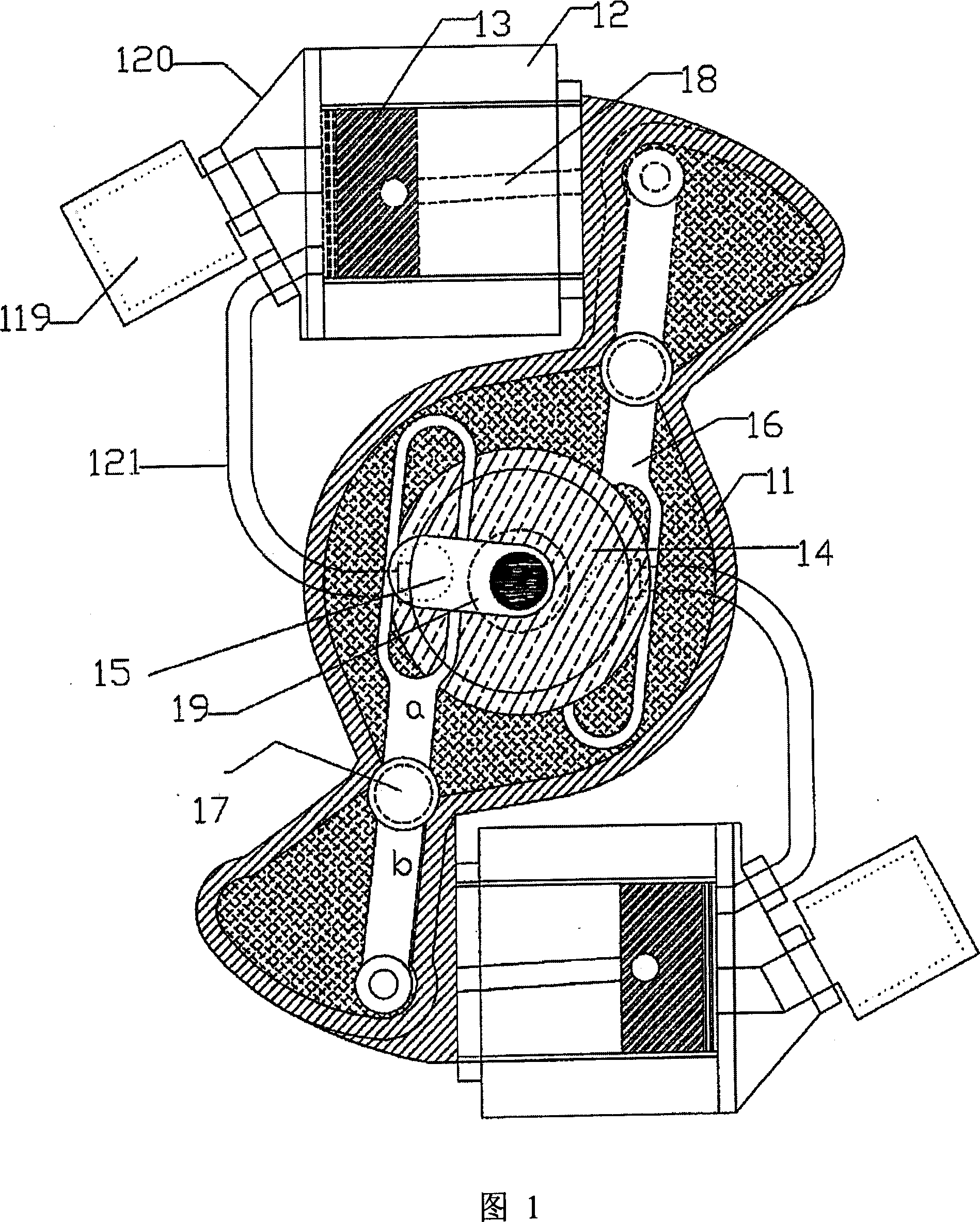
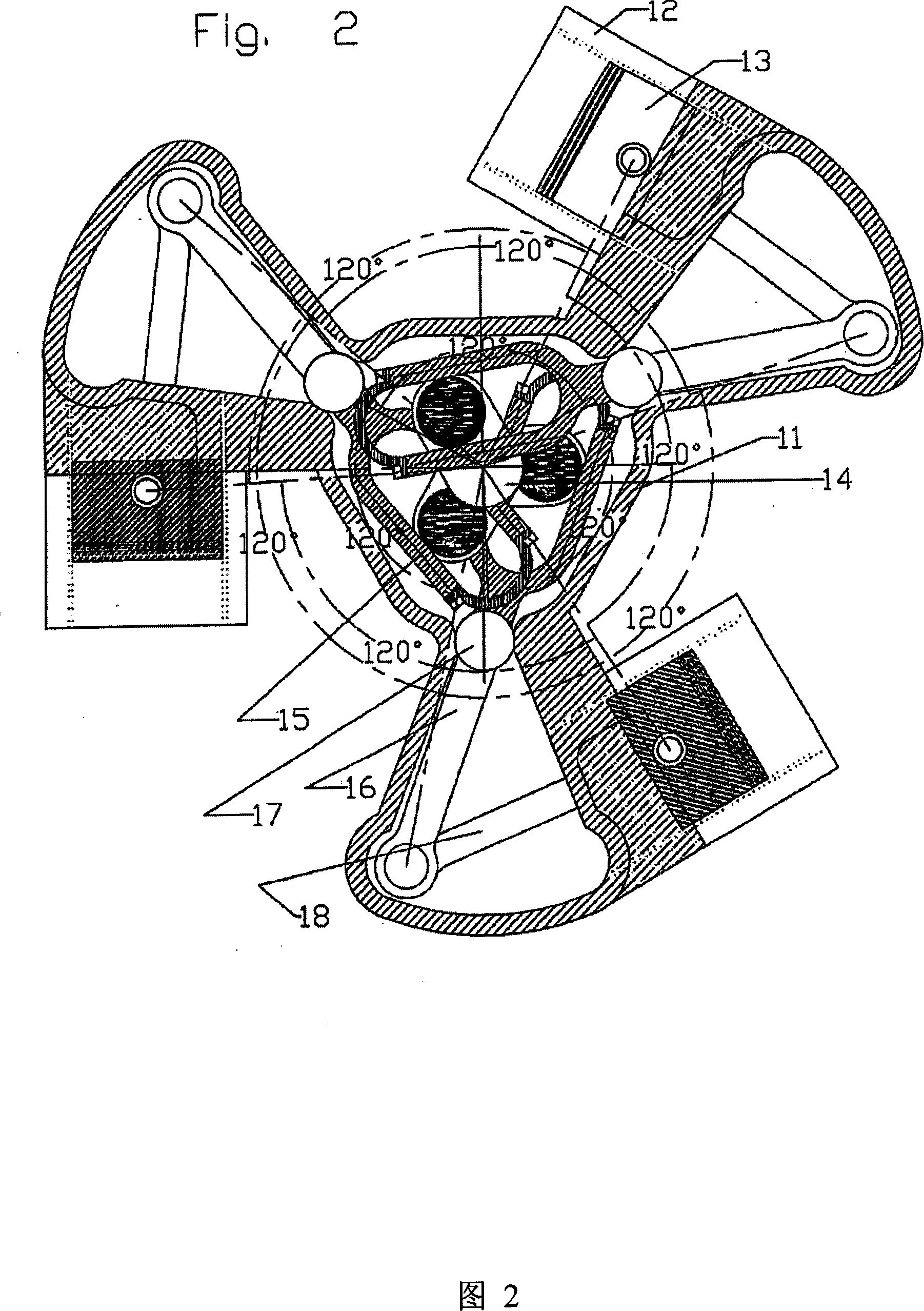
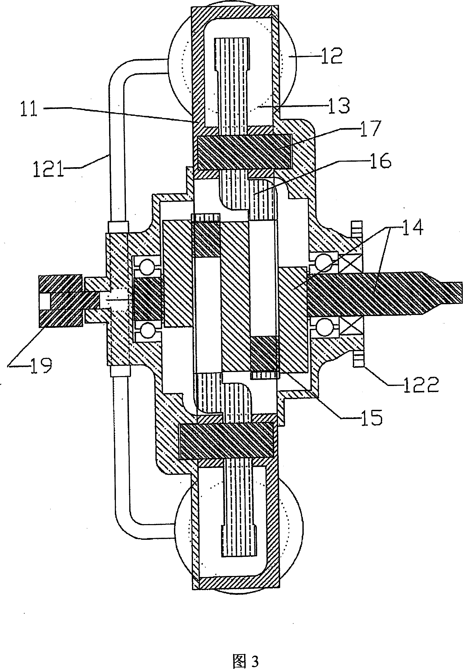
[0021] It can be seen from Figure 1 that the object of the present invention, namely an energy recovery device in a motor vehicle, comprises in the solution shown in Figure 1 a balanced rotary compressor with tangential pistons, including two Pulley module (11) of cylinder (12) and crank (14) with two pins (15). Upon activation of the brake connected to the drive shaft by the clutch, the assembly rotates and the crank (14) remains fixed relative to the system or support. After said rotation has started, the inner arm "a" of the swivel rod (16) slides on the pin (15) of the crank (14), since the crank (14) is fixed, this makes the swivel rod (16) relative to its The shaft (17) is inclined. This angular motion is transferred to the piston (13) via the outer arm "b" and the connecting rod (18). In this way, each rotation of the pulley module drives the piston to complete a complete cycle.

[0022] The cylinder (12) is completely reversed, the piston (13) in the cylinder (12) i...


PUM


Abstract

The invention relates to a mechanism for the recovery of energy in self-propelled vehicles. The inventive mechanism consists of either: (a) a balanced rotary compressor with tangential pistons, comprising two or more cylinders which are connected to a crank having two or more pins; or (b) a rotary compressor with tangential pistons, comprising an extendible crank. The novel system enables the recovery of wasted energy in motor vehicles in the form of pneumatic pressure for the possible use thereof in auxiliary systems belonging to the vehicle or in the engine.

Description

technical field [0001] The present invention relates to a new system for energy recovery in self-propelled vehicles by means of balanced rotary compressors or rotary compressors. The balanced rotary compressor has tangential pistons containing two or more cylinders connected to a crank having two or more pins; or, The rotary compressor has tangential cylinders including extendable cranks. This new system makes it possible to recover wasted energy in motor vehicles in the form of pneumatic pressure for use in auxiliary systems. The invention belongs to the field of vehicles or engines. Background technique [0002] Currently, most of the energy generated by the motor vehicle's engine is consumed in the deceleration system and the continuous braking system, which leads to additional consumption especially in large cities. [0003] In addition to the above disadvantages, the main disadvantage of rotary compressors with tangential pistons is that the elements with internal sh...

Claims


Application Information

Patent Timeline
IPC IPC(8): B60K6/12F01B5/00
CPCY02T10/6208Y02T10/62B60K6/12B60K25/00F04B1/005F04B39/0094
Inventor 弗朗西斯科·哈维尔·路易斯·马丁内兹
Owner 弗朗西斯科·哈维尔·路易斯·马丁内兹
Why Eureka
Try Eureka