Microwave heating method and apparatus

A microwave heating device and microwave heating technology are applied in microwave heating, heating methods, electric heating devices and other directions, which can solve the problems of obtaining satisfaction and increasing temperature distribution, and achieve the effect of improving the final state.

Inactive Publication Date: 2007-04-18
PANASONIC CORP
View PDF3 Cites 7 Cited by
  • Summary
  • Abstract
  • Description
  • Claims
  • Application Information

AI Technical Summary

Problems solved by technology

However, even with these methods, satisfactory results cannot always be obtained especially when thawing frozen foods, and depending on the heating conditions, the temperature distribution increases, which will lead to the local cooking phenomenon

Method used


Image

  • Microwave heating method and apparatus
  • Microwave heating method and apparatus
  • Microwave heating method and apparatus

Examples


Embodiment Construction

[0089] Some of microwave heating method and microwave heating device of the present invention are described in detail now with reference to accompanying drawing

[0090] preferred embodiment.

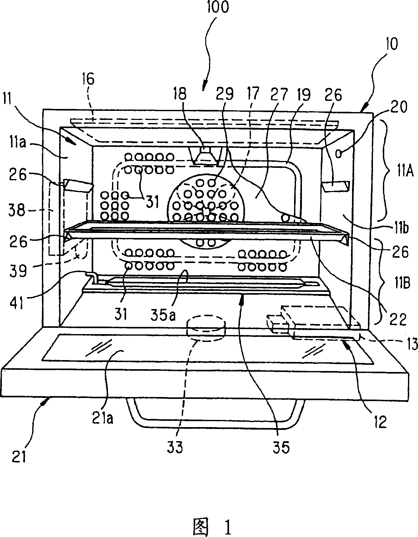
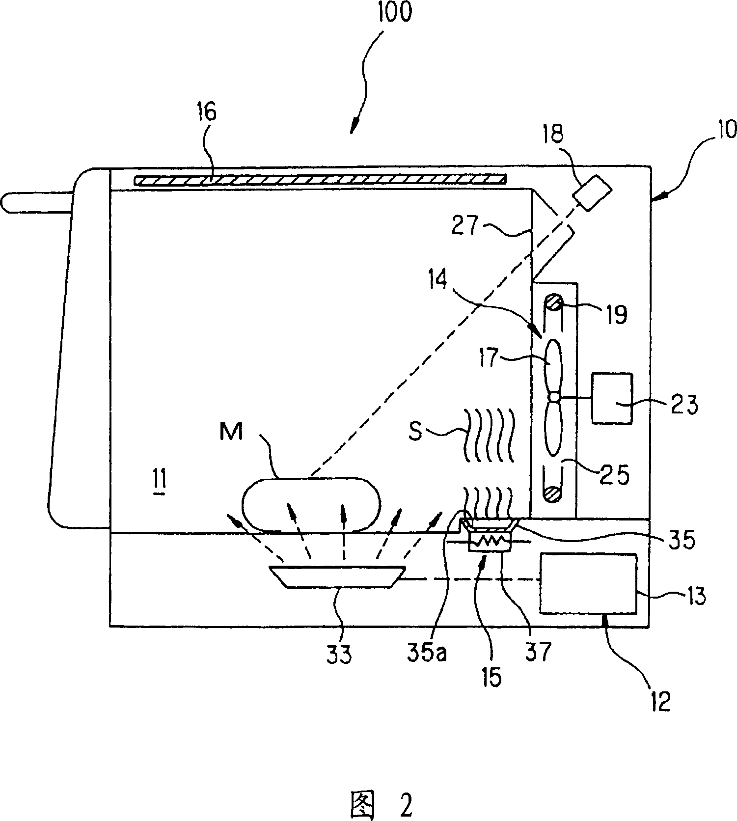
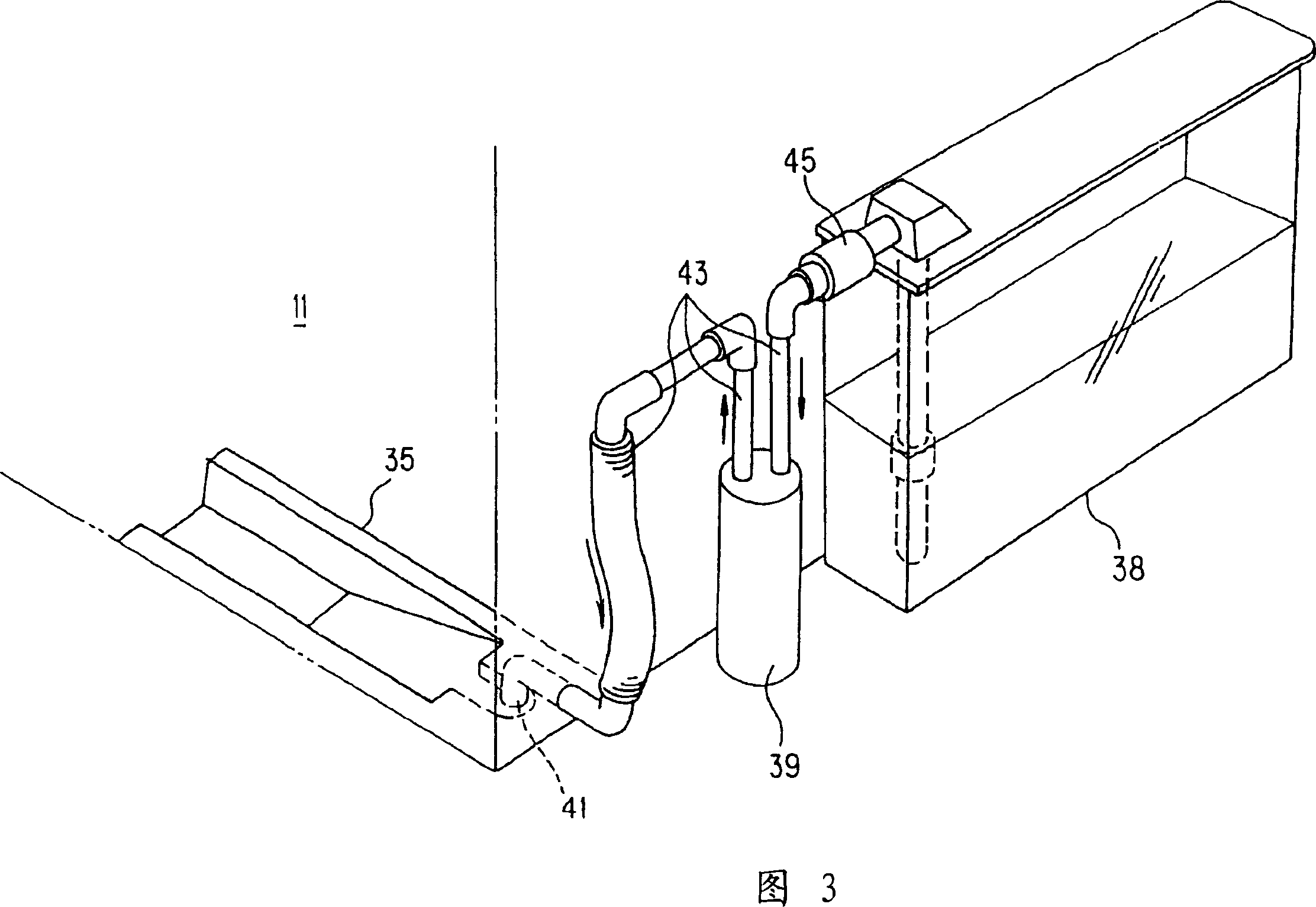
[0091] Fig. 1 is a front view of the microwave heating device of the present invention, which shows the situation that the opening and closing door is in an open state, Fig. 2 is an explanatory diagram of the basic operation of the microwave heating device, and Fig. 3 is a water supply channel leading to the steam supply part Explanatory diagram, Figure 4 is a block diagram of the control system for controlling the microwave heating device.

[0092] Microwave heating device (hereinafter referred to as cooking device) 100 is a kind of cooking device, as shown in Figure 1, it provides at least one of microwave and steam S to the heating chamber 11 that stores the items to be heated, so as to heat the items to be heated heat treatment. The cooking device 100 includes: a magnetron 13 that...


PUM


Abstract

It is intended to suppress local heating peculiar to microwave heating to ensure uniform heating of a heating subject so as to provide improved results of heating. A microwave heating method for heating a heating subject by supplying microwaves to a heating chamber (11) having the heating subject carried therein, the method comprising the steps of supplying microwaves into the heating chamber (11) to heat the heating subject, measuring the temperature of the heating subject to detect whether or not a predetermined temperature difference is produced in the temperature distribution of the heating subject, and supplying fine particles of water into the heating chamber (11) when a predetermined temperature difference is produced so as to change the dielectric constant distribution state in the heating chamber (11), thereby changing the electric field distribution produced by the microwaves supplied into the heating chamber (11).

Description

technical field [0001] The invention relates to a microwave heating method and device for high-frequency heating (dielectrically heating) objects to be heated. Background technique [0002] In a microwave oven as a representative microwave heating device, microwaves radiated from a magnetron are transmitted into a heating chamber via a waveguide to form a standing wave in the heating chamber. According to the electric field component of the standing wave and the dielectric loss of the object to be heated, Items to be heated generate heat. Energy P[W / m] absorbed by the item to be heated per unit volume 3 ] can be expressed by the following equation: [0003] That is, P=(5 / 9)εr·tanδ·f·E 2 ×10 -10 [W / m 3 ], where E[V / m] represents the applied electric field strength, f[Hz] represents the frequency, εr represents the relative permittivity of the object to be heated (the real part of the dielectric constant), and tanδ represents the dielectric constant of the object to be he...

Claims


Application Information

Patent Timeline
Patent Type & Authority Applications(China)
IPC IPC(8): F24C7/02H05B6/74F24C1/04F24C15/32H05B6/68
CPCH05B6/6479H05B6/704F24C1/04H05B6/687F24C15/327H05B6/74F24C1/14
Inventor 吉野浩二信江等隆稻田育弘
Owner PANASONIC CORP
Why Eureka
Try Eureka