
Automatic checking device of elevator and automatic checking method

A technology of automatic inspection and detection device, applied in the direction of transportation, packaging, elevators, etc., can solve the problems of difficult adjustment and false detection, and achieve the effect of reducing the cost of the device, preventing false detection, and reliable detection

Active Publication Date: 2007-04-25
MITSUBISHI ELECTRIC BUILDING SOLUTIONS CORP
View PDF2 Cites 10 Cited by
  • Summary
  • Abstract
  • Description
  • Claims
  • Application Information

AI Technical Summary

Problems solved by technology

[0007] In addition, in the elevator inspection device disclosed in Patent Document 2, there is a possibility of erroneous detection by measuring external sounds other than the hoistway.
And, the reference of the noise level differs for each hoistway, therefore, the adjustment of the reference for determining the noise level becomes difficult

Method used


Image

  • Automatic checking device of elevator and automatic checking method
  • Automatic checking device of elevator and automatic checking method
  • Automatic checking device of elevator and automatic checking method

Examples


Embodiment approach 1

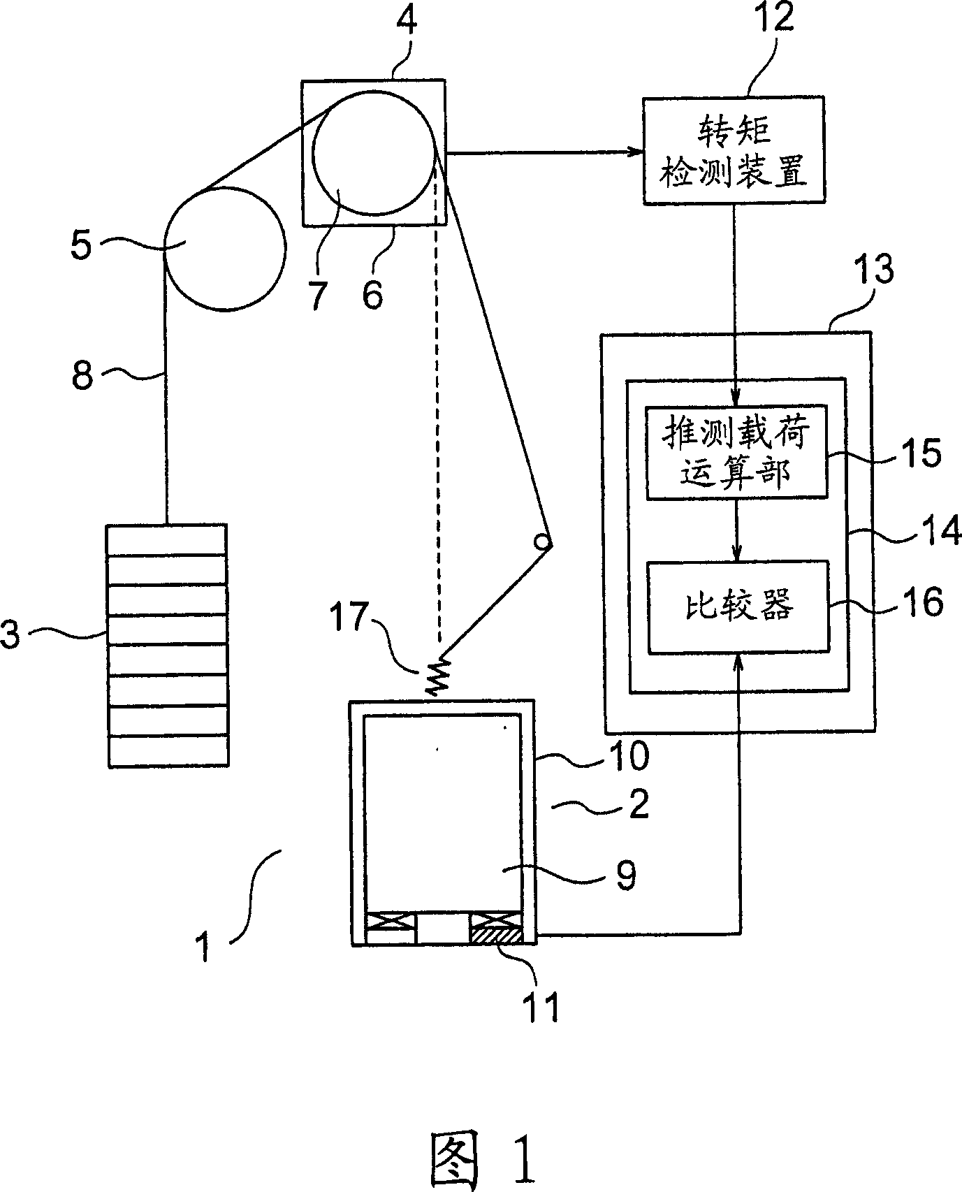
[0017] Fig. 1 is a block diagram showing an elevator provided with an automatic inspection device according to Embodiment 1 of the present invention. In FIG. 1 , a hoistway 1 is provided with a liftable car 2 and a counterweight 3 . On the upper part of the hoistway 1, there are: a traction machine (driver) 4 for lifting the car 2 and the counterweight 3; and a deflector pulley 5 .

[0018] The hoisting machine 4 has: a hoisting machine main body 6 including a motor; and a driving sheave 7 rotated by the hoisting machine main body 6 . A plurality of main ropes 8 are wound around the drive sheave 7 and the deflection sheave 5 . One end of each main rope 8 is connected to the upper portion of the car 2 , and the other end of each main rope 8 is connected to the upper portion of the counterweight 3 . The car 2 and the counterweight 3 are suspended in the hoistway 1 by respective main ropes 8 .

[0019] The car 2 has: a car chamber 9; and a car frame 10 that supports the car ch...

Embodiment approach 2

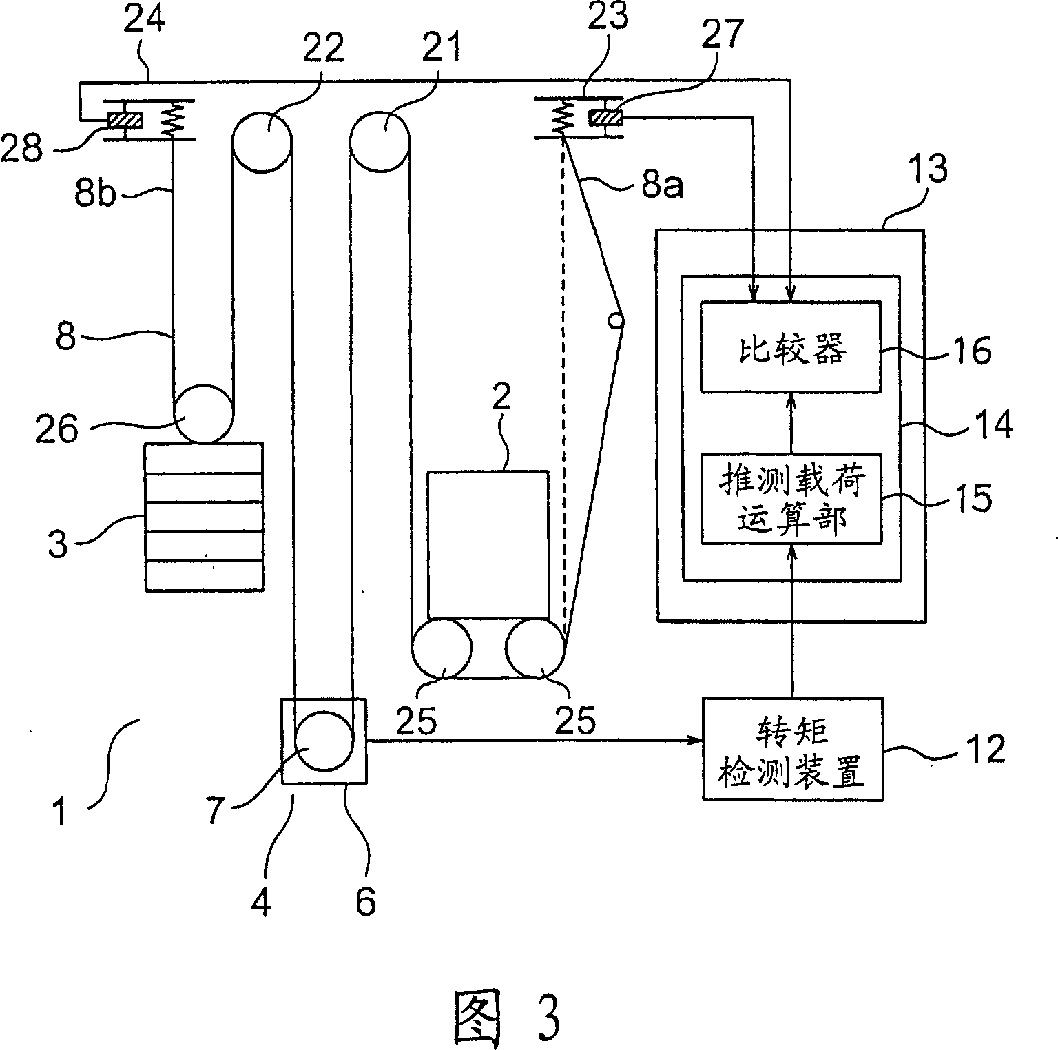
[0037] Fig. 3 is a block diagram showing an elevator provided with an automatic inspection device according to Embodiment 2 of the present invention. In the figure, the hoisting machine 4 is installed in the lower part of the hoistway 1 . A plurality of main ropes 8 are wound around the driving sheave 7 of the hoisting machine 4 . The car 2 and the counterweight 3 are suspended by respective main ropes 8 .

[0038] In the upper part of the hoistway 1, a car-side return sheave 21 and a counterweight-side return sheave 22 around which the main ropes 8 are respectively wound are provided. In addition, a first rope end device 23 connected to one end 8 a of each main rope 8 , and a second rope end device 24 connected to the other end 8 b of each main rope 8 are provided in the upper part of the hoistway 1 .

[0039] A pair of car hanging sheaves 25 are provided at the lower portion of the car 2 . In addition, a counterweight suspension wheel 26 is provided on the upper portion o...


PUM


Abstract

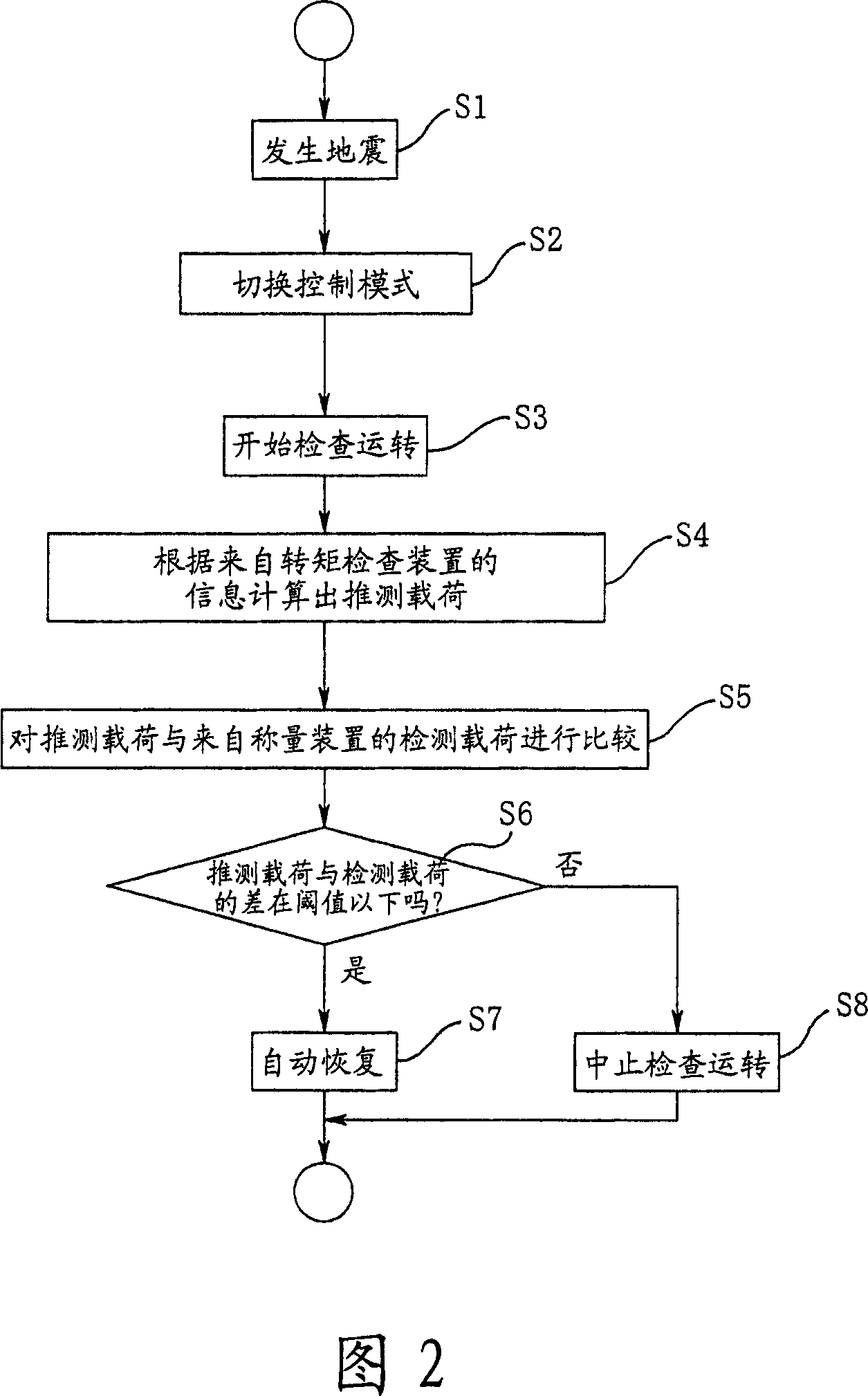
The present invention provides an automatic checking device of elevators and an automatic checking method capable of detecting abnormity in elevators more reliably, with reduced cost. An elevator car and an elevator counterweight are hung by a main cord of a driving rope sheave winding on a traction machine. A weighing device is mounted on the elevator car to detect the loading of the elevator car as a detecting load. The rotating torque of the driving rope sheave is obtained by measuring the torque current of the traction machine through a torque detecting device. The information respectively from the weighing device and the torque detecting device are introduced into a judgment device where the loading of the elevator car calculated according to information of the torque detecting device is regarded as presumed loading. In addition, whether there is an abnormity capable of being judged by comparing the presumed loading and the detecting loading in the judgment device.

Description

technical field [0001] The present invention relates to an elevator automatic inspection device for automatically inspecting an elevator after an earthquake, and an elevator automatic inspection method. Background technique [0002] Conventionally, there has been proposed an elevator abnormality detection device that measures the vibration of the car periodically, and judges whether the current vibration level is abnormal based on past maximum and minimum vibration levels. Vibration levels measured in the past are stored in memory (for example, refer to Patent Document 1). [0003] Furthermore, conventionally, there has been proposed an inspection device for an elevator that detects abnormal sounds in a hoistway using a microphone installed in a car (for example, refer to Patent Document 2). [0004] Patent Document 1: Japanese Patent Laid-Open No. 10-59645 [0005] Patent Document 2: Japanese Patent Laid-Open No. 6-247657 [0006] However, in the elevator abnormality det...

Claims


Application Information

Patent Timeline
Patent Type & Authority Applications(China)
IPC IPC(8): B66B5/00
Inventor 渡边诚治福井大树汤村敬西山秀树河原利昭
Owner MITSUBISHI ELECTRIC BUILDING SOLUTIONS CORP
Learn More