Centrifugal pump having extrusion chamber with subchannel

A technology of shunt channels and pressure chambers, which is applied to parts, pumps, and pump components of elastic fluid pumping devices, can solve problems such as prolonged friction time, reduced flow efficiency, unfavorable safety, and environmentally friendly operation, and achieves The effect of reducing and shortening friction opportunities and time, improving flow efficiency, and reducing cavitation

Inactive Publication Date: 2007-04-25
宣伯民
View PDF0 Cites 5 Cited by
  • Summary
  • Abstract
  • Description
  • Claims
  • Application Information

AI Technical Summary

Problems solved by technology

This kind of pump has many known advantages, but as far as the pressure chamber is concerned, there are also some shortcomings that affect the improvement of efficiency and are not conducive to safe and environmentally friendly operation.
The liquid flowing out of the impeller flow channel is continuously thrown to the extrusion chamber at high speed, which impacts and interferes with the original liquid in the extrusion chamber. Coupled with the high-speed rotation of the impeller, the flow state of the liquid in the extrusion chamber is seriously deteriorated, greatly reducing the flow rate. efficiency
Since the liquid in the extrusion chamber cannot flow out smoothly, the static pressure in the extrusion chamber is high, which not only increases the backflow and leakage losses, but also reduces the overall flow rate, and also aggravates the occurrence of cavitation
Due to the deterioration of the liquid flow state, the chance of friction with the high-speed rotating impeller will increase, and the friction time will be prolonged, which will increase the temperature of the extrusion chamber and cause hidden dangers to safe operation.
When the pump is operated under non-design conditions, the velocity of the liquid flow in the extrusion chamber will change, which will destroy the constant velocity flow in the chamber, and the radial pressure acting on the outer edge of the impeller will become unevenly distributed, and the rotor will be affected by the radial pressure. The action of thrust will generate noise and shorten the service life of the bearing

Method used


Image

  • Centrifugal pump having extrusion chamber with subchannel

Examples


Embodiment Construction

[0014] The present invention will be further described below in conjunction with the accompanying drawings.

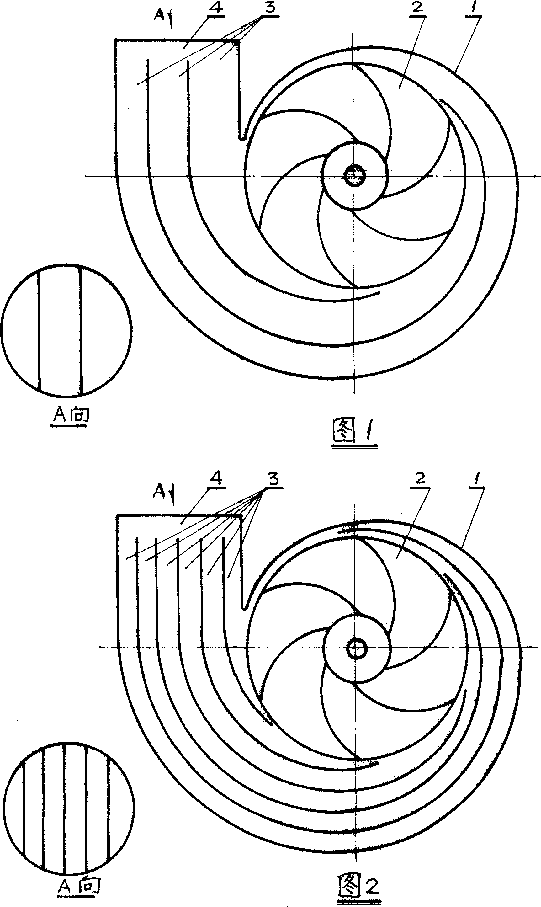
[0015] In the figure, the extrusion chamber in the extrusion chamber shell 1 has been occupied by the flow channel 3, and the arrangement of the flow channel 3 presents a center-symmetrical arrangement centered on the center of the impeller, and the liquid flow thrown out of the flow channel of the impeller 2 is timely It is introduced into the sub-flow channel 3 and flows into the main flow channel 4 smoothly. As for the number of shunt channels 3, the more the shunt, the more obvious the shunt effect, but it will increase the difficulty of the manufacturing process, so three to six are more suitable. For the manufacturing process of the flow channel 3, whether it is cast together with the pump casing's extrusion chamber or embedded after it is manufactured separately, the wall of the flow channel should be smooth to reduce the resistance along the process. Most of t...


PUM


Abstract

The invention discloses a centrifugal pump with dividing channel in discharge chamber with the purpose that fluid flow pattern in discharge chamber is improved so as to improve pump running status. It is provided with simple structure and easy machining. The invention comprises pump shell, vane wheel, driving part and three and more than three dividing channels in discharge chamber. Compared with current known centrifugal pump the invention can lead fluid flow in time and not interference with each other so that improved efficiency, increased flow quantity, lessened air corrosion and decreased noise are realized. It is provided with prolonged service life and stable running.

Description

technical field [0001] The invention relates to the field of centrifugal pumps, in particular to a centrifugal pump in which a discharge chamber is provided with subflow channels. Background technique [0002] Statistics show that more than 30% of the total electricity consumption in the country is consumed by pumps and fans. It can be seen that pumps and fans occupy an important position in my country's national economic construction. From the scope of use of various types of pumps and fans, centrifugal pumps are the most widely used in pumps. Therefore, the present invention relates to the field of centrifugal pumps, in particular to centrifugal pumps in which the common extrusion chamber structure is helical. This pump has many known advantages, but as far as the pumping chamber is concerned, it also has some disadvantages that affect the improvement of efficiency and are not conducive to safe and environmentally friendly operation. The liquid ...

Claims


Application Information

Patent Timeline
Patent Type & Authority Applications(China)
IPC IPC(8): F04D29/44F04D29/02
Inventor 宣伯民
Owner 宣伯民
Why Eureka
Try Eureka