Lens barrel

A technology for lens barrels and components, applied in installation, television, optics, etc., can solve problems such as image jitter and image loss, and achieve the effects of simple mechanism, prevention of gear strength reduction, and smooth rotation operation.

Inactive Publication Date: 2007-04-25
SONY CORP
View PDF2 Cites 12 Cited by
  • Summary
  • Abstract
  • Description
  • Claims
  • Application Information

AI Technical Summary

Problems solved by technology

As a result, when the linear moving member is spring-biased in the optical axis direction by the elastic force of an appropriate mechanism such as a coil spring as described above, backlash occurs due to a change in the inclination of the cam groove of the cam ring, and then unavoidable Disadvantages of noise, image shaking, and image loss

Method used


Image

  • Lens barrel
  • Lens barrel
  • Lens barrel

Examples


Embodiment Construction

[0048] According to the present invention, there is provided a lens barrel in which maintaining smooth rotational operation of a rotating member makes it possible to suppress image loss, image shake, and occurrence of abnormal sound (noise) generated when operating the lens barrel.

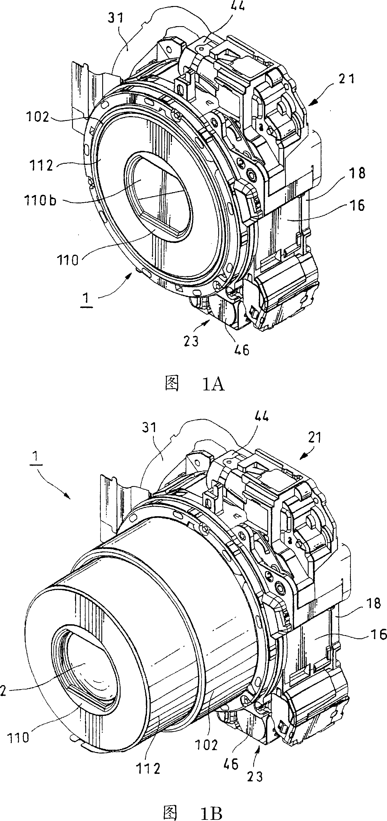
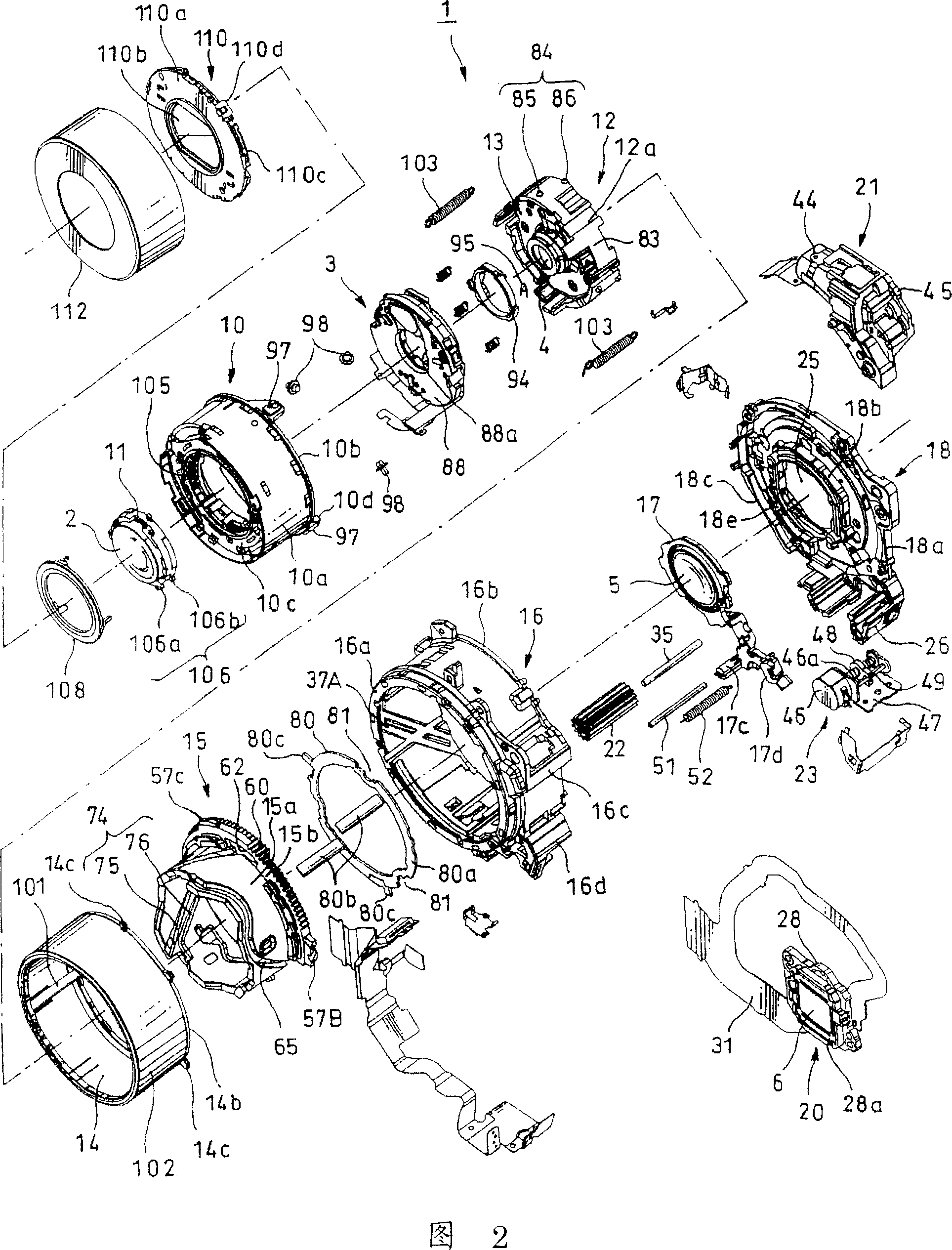
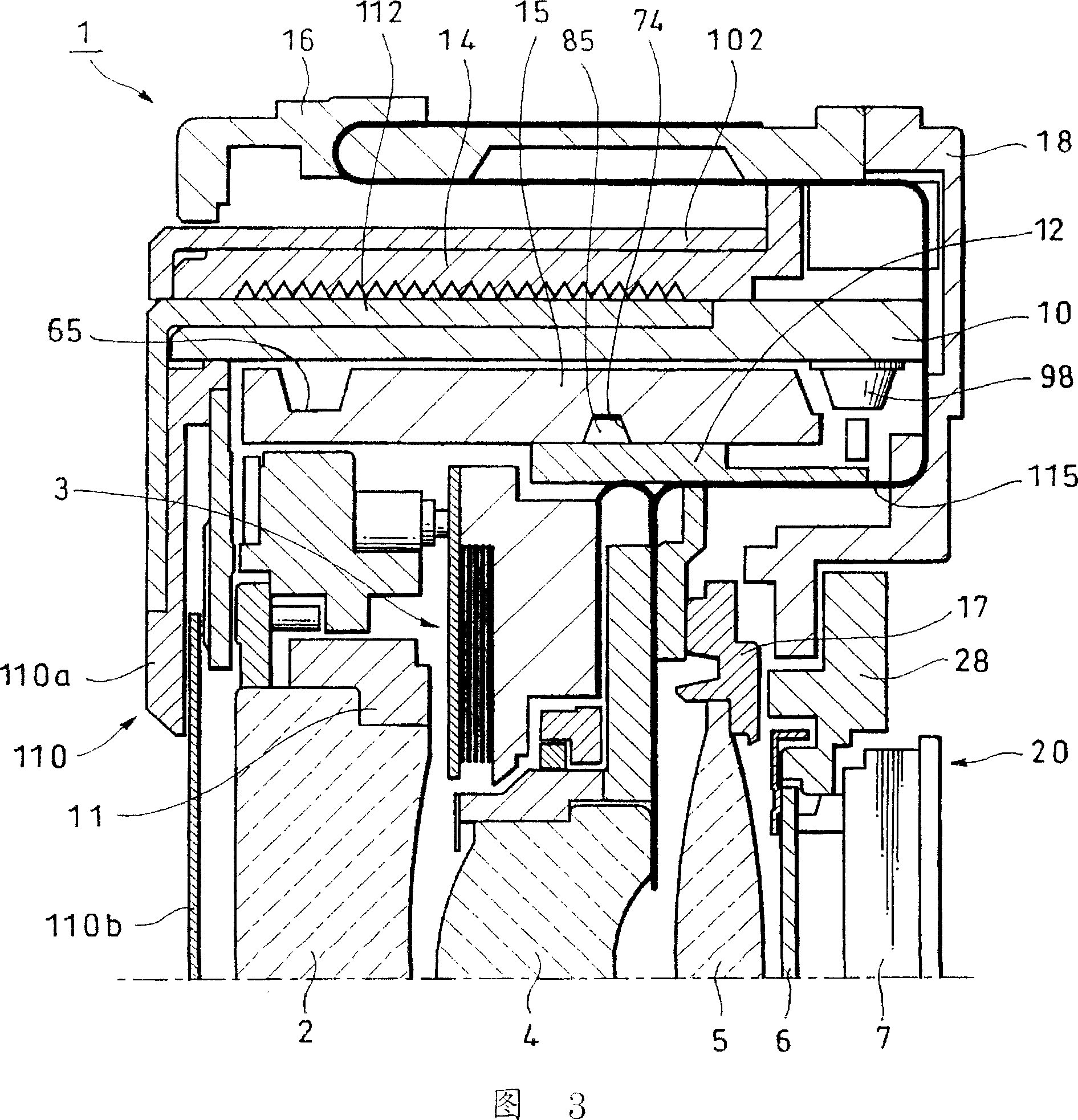
[0049] Embodiments of the present invention will be described below with reference to the drawings. 1A, 1B to 37 are diagrams for explaining an embodiment of the present invention. More specifically, FIGS. 1A and 1B are perspective views showing a first embodiment of the lens barrel cam mechanism according to the present invention, respectively, wherein FIG. 1A shows the retracted state of the lens barrel, and FIG. 1B shows the extended state of the lens barrel. . Fig. 2 is an exploded perspective view of the lens barrel shown in Figs. 1A and 1B. Fig. 3 is a sectional view showing a retracted state of the lens barrel. Fig. 4 is a sectional view showing a state in which the lens barrel is extend...


PUM


Abstract

A lens barrel including a linearly movable member to hold an optical element and which can be moved in an optical direction of the optical element and which includes a cam follower, a rotary member rotatable relative to the linearly movable member and which includes on its circumferential surface a cam groove with which the cam follower is slidably engaged, a gear portion formed integrally with or separately of the rotary member in order to rotate the rotary member, a drive gear and a power source including a gear train meshed with the drive gear. Power from the power source is transmitted from the drive gear to the gear portion to rotate the rotary member. This lens barrel includes a gear spring-biasing member for spring-biasing the drive gear to one of directions in which spur gear is extended under spring force.

Description

technical field [0001] The present invention relates to a lens barrel in which a linear moving member connected to the lens barrel can move back and forth by rotating a rotating member with a driving gear. Background technique [0002] So far, for example, cited Patent Document 1 has described such a barrel cam mechanism. That is, the technology described in cited Patent Document 1 relates to a light amount adjusting device located in an optical path of an optical system and a camera including the light amount adjusting device therein (hereinafter referred to as "first prior art example"). The camera according to this first prior art example includes an optical system having a first lens group whose light exit surface is formed as a concave surface and a second lens group comprising a convex surface from the first lens group. The light of the lens group is incident on the convex surface, and the optical system can be zoomed by its optical aperture (iris) position between th...

Claims


Application Information

Patent Timeline
Patent Type & Authority Applications(China)
IPC IPC(8): G02B7/02
CPCG03B17/04H04N5/2254H04N23/53H04N23/55G02B7/08G03B3/10
Inventor 白方圣
Owner SONY CORP
Why Eureka
Try Eureka