Check patentability & draft patents in minutes with Patsnap Eureka AI!

Laser diode control circuit loop

一种激光二极管、控制回路的技术,应用在激光器、激光器零部件、半导体激光器等方向,能够解决无法符合需求、激光二极管无法正常工作等问题,达到成品率高、消耗功率少的效果

Inactive Publication Date: 2007-05-02
TM TECHNOLOGY INC
View PDF0 Cites 2 Cited by
  • Summary
  • Abstract
  • Description
  • Claims
  • Application Information

AI Technical Summary

Problems solved by technology

Obviously, the supply voltage 12 is insufficient, which will make the driving circuit 10 of the laser diode unable to work normally
[0008] Low power consumption circuit design is currently the mainstream product. The supply voltage 12 of many electronic products is designed from the previous high voltage (example: 5V), and gradually uses low voltage (example: 3.3V) to supply its operating voltage, so use The driving circuit 10 of the existing high voltage laser diode will not be able to meet the needs of today's circuit design
[0009] For this reason, how to design a control circuit of a laser diode with high-speed operation and low supply voltage for the above-mentioned shortcomings of using a high-voltage operation for the driving circuit of the existing laser diode, this is the key point of the present invention

Method used


Image

  • Laser diode control circuit loop
  • Laser diode control circuit loop
  • Laser diode control circuit loop

Examples


Embodiment Construction

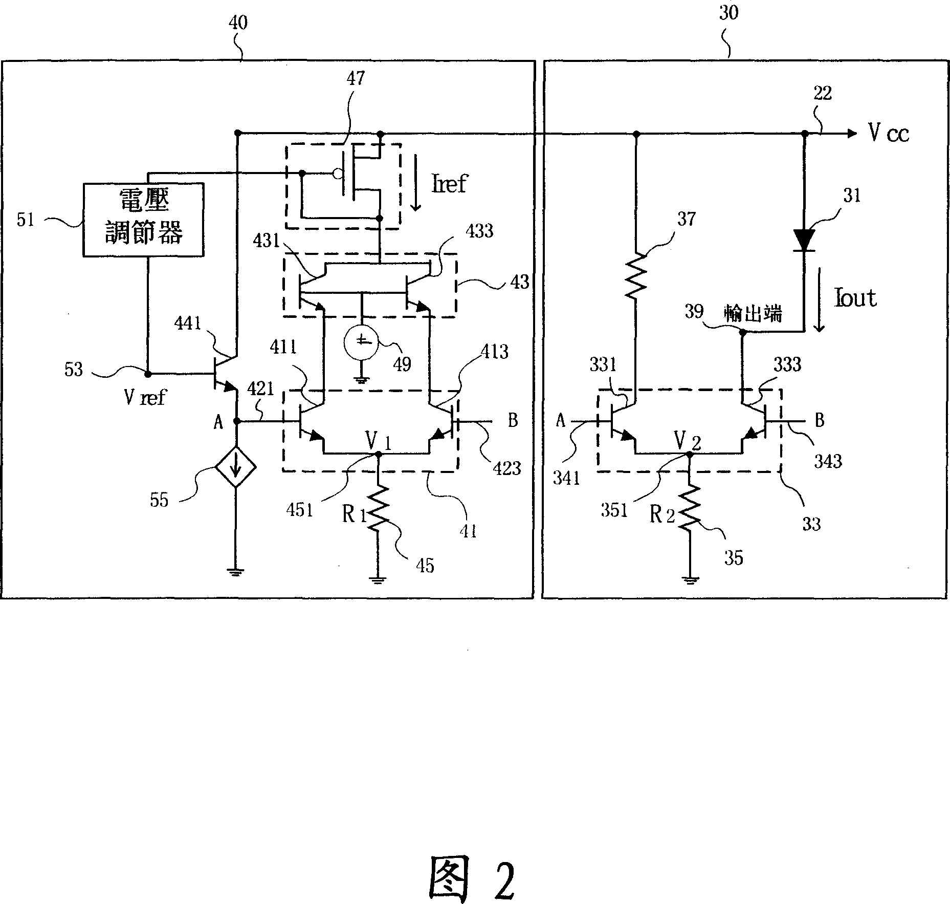
[0019] First, please refer to FIG. 2, which is a circuit diagram of a preferred embodiment of the present invention. As shown in the figure, the control loop 20 of the laser diode of the present invention mainly includes a reference circuit 40 and a driving circuit 30.

[0020] The reference circuit 40 has a programmable reference current Iref, and the reference current Iref is generated by a current source switch unit 47. The current source switch unit 47 can be a P-type MOSFET. The gate terminal and the drain terminal are connected together, and the source terminal is connected with a supply voltage 22.

[0021] In addition to the current source switch unit 47, the reference circuit 40 further includes: a first high-speed switch unit 43, a second high-speed switch unit 41, an emitter follower 441, and a voltage regulator 51.

[0022] Among them, the second high-speed switch unit 41 includes a third transistor 411 and a fourth transistor 413. The third transistor 411 and the four...


PUM


Abstract

A laser diode control circuit loop comprises a reference circuit with a programmable reference current, a first endpoint thereof providing a first voltage and a second endpoint thereof providing a second voltage, according as the reference current passing through the first endpoint and the second endpoint; and a driving circuit, a third endpoint thereof connected to the first endpoint of the reference circuit, a fourth thereof connected to the second endpoint of the reference circuit, a output end thereof providing a driving voltage and an output current, and the reference current of the reference circuit and the output current of the driving circuit are as direct ratio. With regard to the operation field of the laser diode driving circuit, the operation limitation within low voltage can be got over, according as the output current from the reference current matching.

Description

Technical field [0001] The present invention relates to a laser diode control loop, especially a high-speed and low-voltage laser diode control loop. Through this, the output current can be obtained according to the reference current matching, so that the working range of the laser diode driving circuit can overcome Limitations of low voltage operation. Background technique [0002] With the rapid development of the electronic industry, the performance requirements of electronic products are getting higher and higher, and the functions of the products are diversified, and the circuit design is becoming more and more complicated. When a sophisticated circuit is operated at a high supply voltage, it will not only cause high power consumption of the circuit and affect the response time of the circuit, but also reduce the yield of the circuit semiconductor manufacturing process. [0003] Generally, the output driving voltage of the existing laser diode driving circuit must be operate...

Claims


Application Information

Patent Timeline
Patent Type & Authority Applications(China)
IPC IPC(8): H01S5/042
CPCH01S5/06808H01S5/042
Inventor 王智扬陈有栋
Owner TM TECHNOLOGY INC
Features
  • R&D
  • Intellectual Property
  • Life Sciences
  • Materials
  • Tech Scout
  • Unparalleled Data Quality
  • Higher Quality Content
  • 60% Fewer Hallucinations
Learn More