Indirect artificial valva outside vein

A valve and vein technology, applied in the field of extravenous indirect artificial valve, can solve the problems of valve insufficiency, affecting daily life and work, insufficiency of deep veins of lower extremities, etc., to maintain integrity and reduce the possible risk of thrombosis Effect

Inactive Publication Date: 2007-05-09
ZHEJIANG UNIV
View PDF0 Cites 20 Cited by
  • Summary
  • Abstract
  • Description
  • Claims
  • Application Information

AI Technical Summary

Problems solved by technology

However, due to other reasons such as congenital valvular poor structure, thrombus blockage or long-term standing weight bearing, valve closure is insufficient. This kind of disease is called deep venous in

Method used


Image

  • Indirect artificial valva outside vein
  • Indirect artificial valva outside vein
  • Indirect artificial valva outside vein

Examples


Embodiment Construction

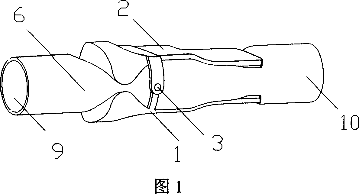
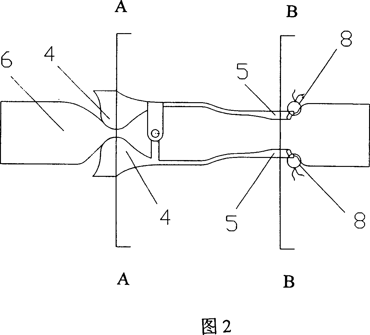
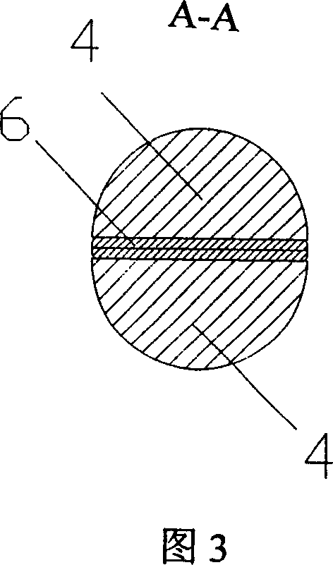
[0018] As shown in Figures 1 and 2, the upper valve body 2 and the lower valve body 1 are connected by valve shafts 3 on both sides; The compression point 5 at the proximal end of the wall, the compression point 4 at the distal end of the blood vessel wall can contact the distal end of the vein 9, and the compression point 5 at the proximal end of the blood vessel wall can contact the proximal end of the vein 10; the upper body of the valve 2 and the proximal end of the blood vessel wall of the lower body 1 The compression points 4 are all fixed with fixed sutures 8 to fix the upper valve body 2, the lower valve body 1 and the vein wall 6.

[0019] The compression area of ​​compression point 4 at the distal end of the vessel wall is smaller than the compression area of ​​compression point 5 at the proximal end of the vessel wall; the compression degree of compression point 4 at the distal end of the vessel wall is greater than that at compression point 5 at the proximal end of ...


PUM


Abstract

An external indirect artificial valve for vein is composed of upper valve body, lower valve body and two side valve axles for connecting said upper valve body with said lower one. The both ends of the artificial valve have respectively the far-end and near-end pressing points to the wall of blood vessel, which are respectively fixed to the far end and near end of vein b suture.

Description

technical field [0001] The invention relates to a medical device, in particular to an extravenous indirect artificial valve for treating deep venous insufficiency of lower limbs. Background technique [0002] In the blood circulation of the whole body of the human body, the return of blood from the lower limbs to the heart against gravity is an important part of the whole blood circulation. There are two main reasons why the blood of the lower limbs can resist gravity and return smoothly. One is that the muscles of the lower legs contract and relax alternately, acting as a muscle pump to squeeze the venous blood wrapped in the muscles to the heart; the other is that in the veins of the entire lower limbs, Generally, there is a venous valve every 10 to 20 centimeters to prevent the backflow of blood. However, due to other reasons such as congenital valvular poor structure, thrombus blockage or long-term standing weight bearing, valve closure is insufficient. This kind of dis...

Claims


Application Information

Patent Timeline
IPC IPC(8): A61F2/02A61B17/00A61L27/06A61L27/34
Inventor 刘颖斌王俊
Owner ZHEJIANG UNIV
Why Eureka
Try Eureka