Laser cutting positioner of drawn component

A positioning device and laser cutting technology, applied in auxiliary devices, laser welding equipment, welding/cutting auxiliary equipment, etc., can solve problems such as increased production costs, inaccurate positioning, and large steel plates

Inactive Publication Date: 2007-05-09
BYD CO LTD
View PDF0 Cites 0 Cited by
  • Summary
  • Abstract
  • Description
  • Claims
  • Application Information

AI Technical Summary

Problems solved by technology

Obviously, this method consumes a lot of steel plates, generally 8-12 steel plates are required for each drawn part, and a large amount of laser cutting is required to cut these steel plates into corresponding sections, so the production cost is significantly increased and the production cost is reduced. production efficiency; in addition, multiple steel plates need to be assembled together, so the structure is unstable, the positioning is inaccurate, and cutting errors are easy to occur; and, since the drawn parts are freely placed on this support, the drawn parts are placed on the laser During the cutting process, deformation occurs due to the release of its own stress, which will also lead to cutting errors

Method used


Image

  • Laser cutting positioner of drawn component
  • Laser cutting positioner of drawn component
  • Laser cutting positioner of drawn component

Examples


Embodiment Construction

[0014] The structure and principle of the present invention will be described in detail below with reference to the accompanying drawings.

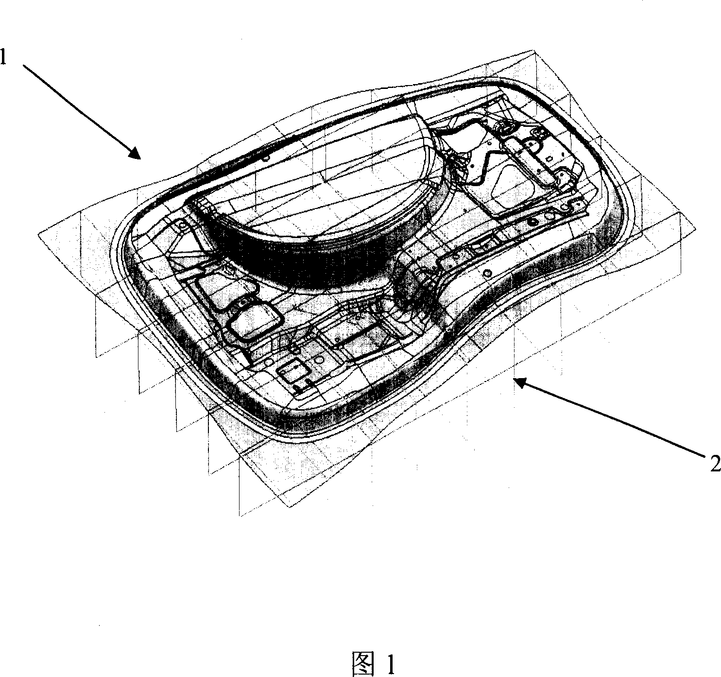
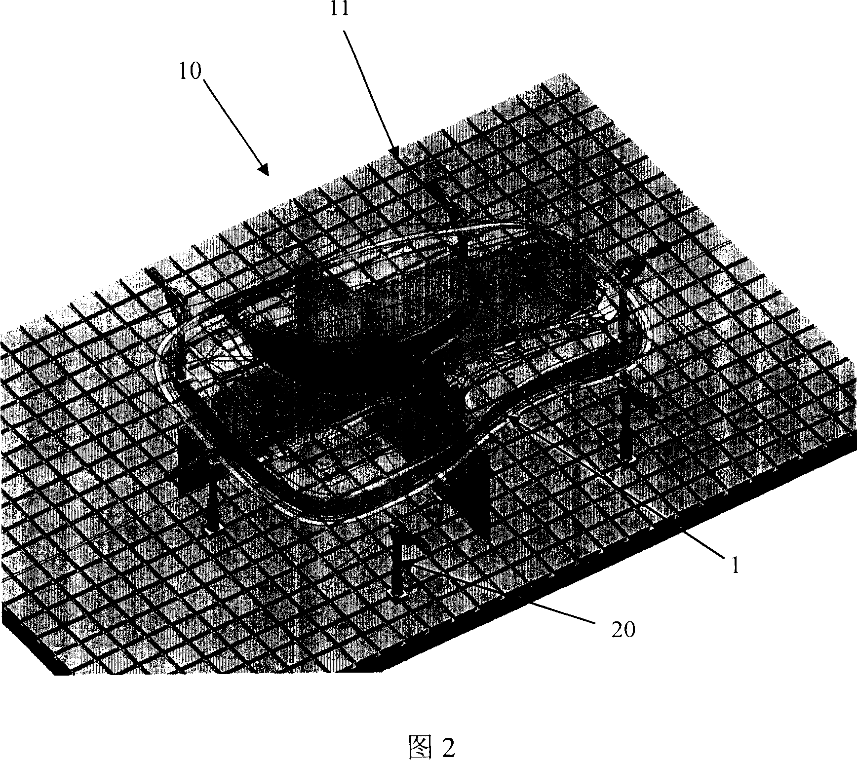
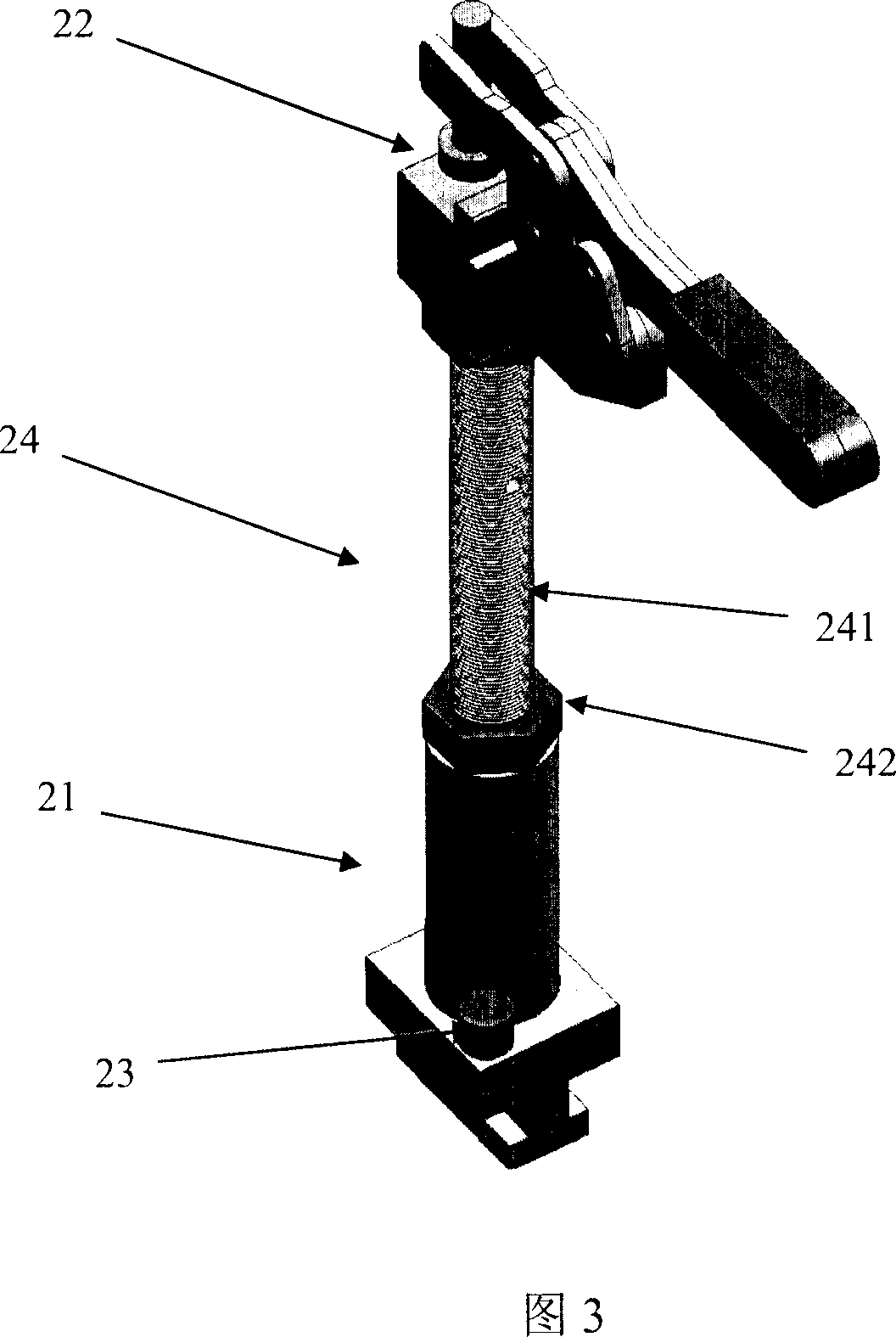
[0015] As shown in Figure 2, the laser cutting and positioning device for drawn parts according to the present invention includes a bottom plate 10 and a plurality of clamping mechanisms 20, wherein there are a plurality of criss-cross guide and positioning grooves 11 on the bottom plate, and each clamp The lower part of the tightening mechanism has a slider 21, and the upper part has a clip 22, and the slider can slide or lock in the guide positioning groove 11.

[0016] The guiding and positioning grooves 11 on the base plate 10 are criss-crossed, just like a Go board. The distance between the guiding and positioning grooves 11 can be determined according to the actual situation, for example, it is 100 mm. The slider 21 can move arbitrarily in these guiding and positioning grooves, and then be positioned to support the drawing member 1...


PUM


Abstract

A locating device for the laser cutting of drawn workpiece is composed of a baseplate with multiple criss-cross guiding-locating slots on it, and multiple fastening mechanisms with the slide block able to slide or be locked in said guiding-locating slot and the top fastener.

Description

technical field [0001] The invention relates to a positioning device for workpieces with complex profiles, in particular to a laser cutting positioning device for drawn parts. Background technique [0002] Drawn parts generally have a relatively complex profile, so at present, when the drawn part is subsequently laser cut, there are often difficulties in positioning the drawn part. [0003] In the prior art, one method is to use the blank holder of the drawing die to position the drawn part. This method needs to put the lower part of the entire drawing die on the laser cutting machine, which is very cumbersome to operate; and due to the limited load-bearing capacity of the laser cutting machine, this method cannot be used when the drawn part is large. [0004] Another method is to reproduce a set of plaster models for each drawn part, and then use the plaster model to position the drawn parts. Obviously, this method is very time-consuming and troublesome, not only will inc...

Claims


Application Information

Patent Timeline
Patent Type & Authority Applications(China)
IPC IPC(8): B23K26/02B23K37/04
Inventor 黄河
Owner BYD CO LTD
Why Eureka
Try Eureka