
Scriber for controlling pressure by magnetic force

A scriber, pressure technology, applied in the direction of manufacturing tools, glass manufacturing equipment, planer/slotting machine, etc.

Inactive Publication Date: 2007-05-09
TOP ENG CO LTD
View PDF1 Cites 7 Cited by
  • Summary
  • Abstract
  • Description
  • Claims
  • Application Information

AI Technical Summary

Problems solved by technology

However, this conventional scribe has problems similar to those of the other conventional art pneumatic scribes described above

Method used

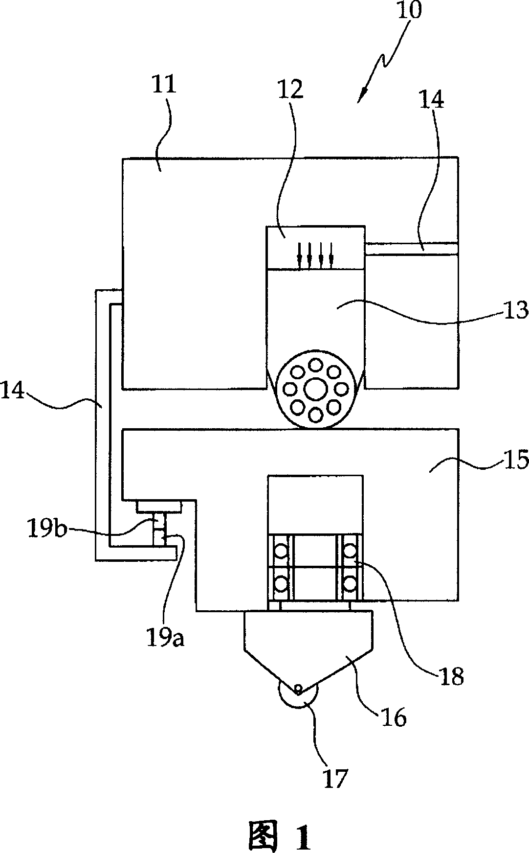
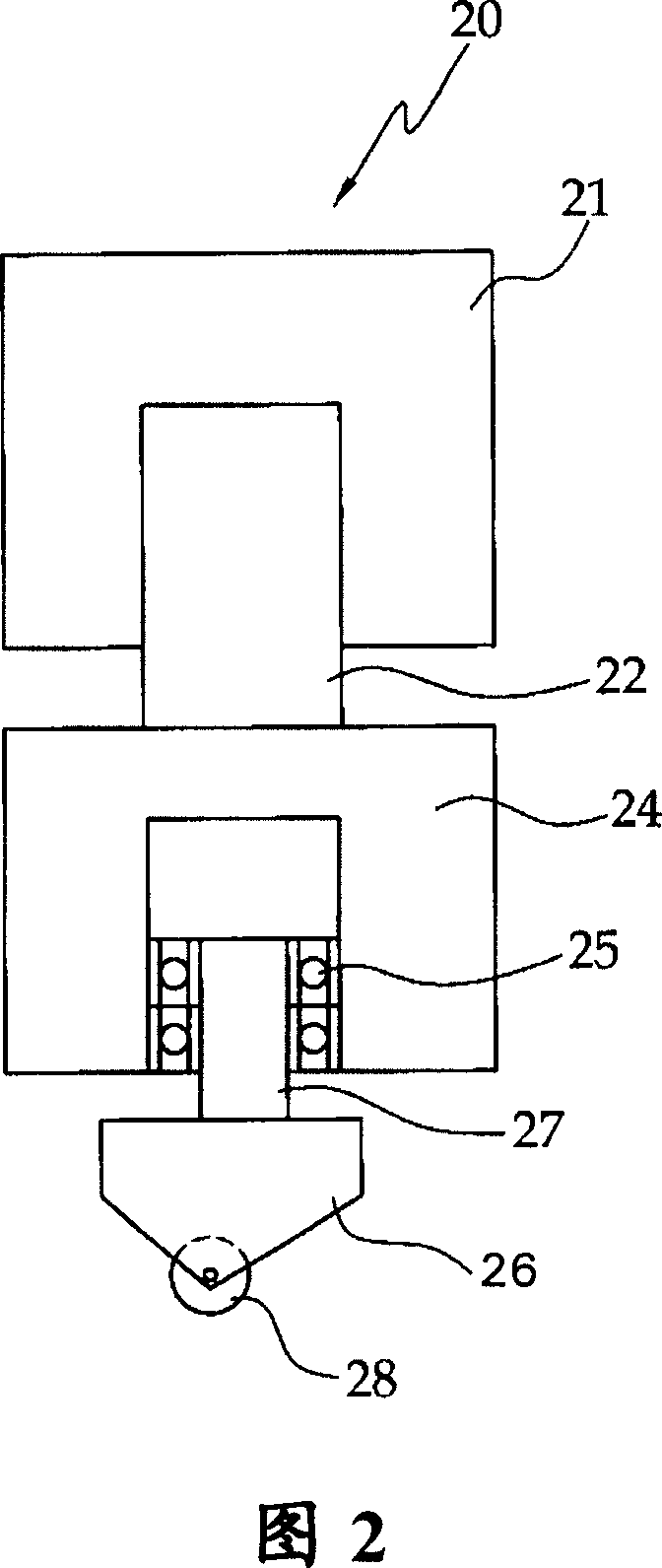
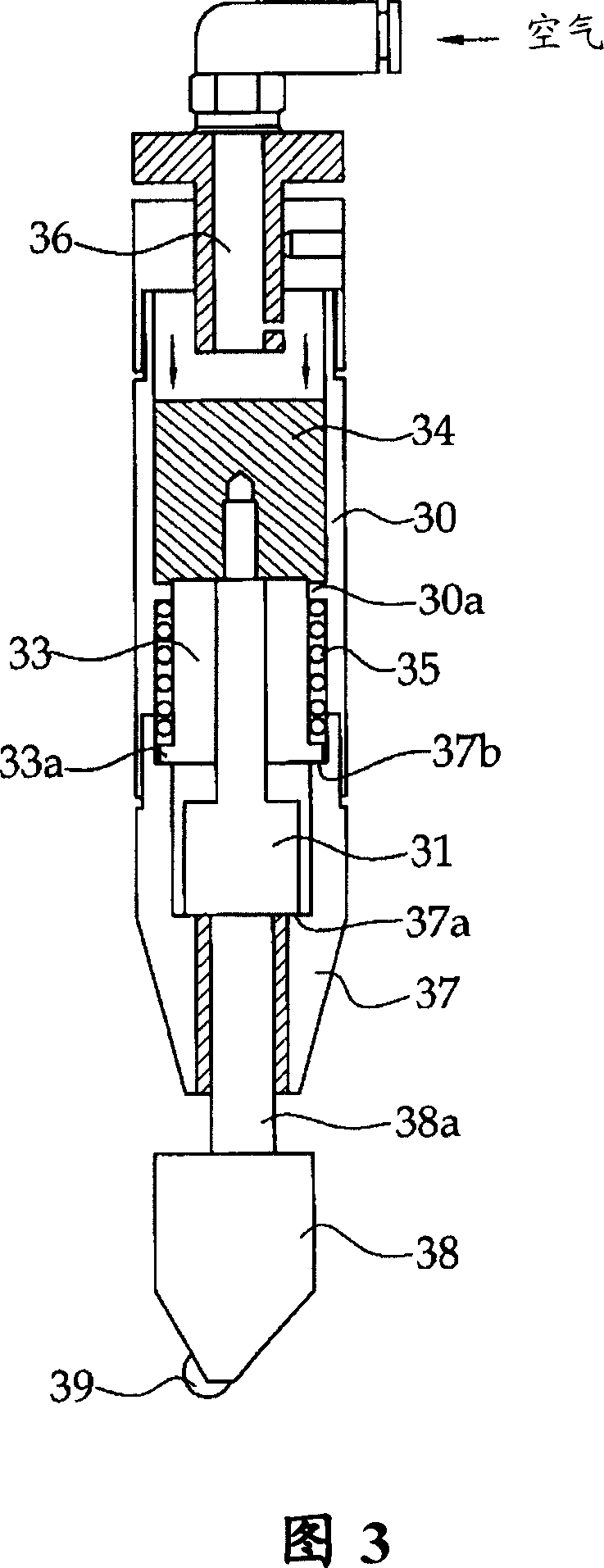

Image

  • Scriber for controlling pressure by magnetic force
  • Scriber for controlling pressure by magnetic force
  • Scriber for controlling pressure by magnetic force

Examples


no. 1 example

[0058] As shown in FIG. 4 , the scribe using magnetic force to control pressure according to the first embodiment of the present invention includes: a head 40 including a pressure applying magnet 46 for a permanent magnet; a movable head 50 including a permanent The pressure of the magnet receives the magnet 52, the movable head 50 is movably connected to the lower end of the head 40; and the wheel holder 56, which is mounted at the movable head 50.

[0059] Head 40 includes housing end 43 , pressure device 44 , and housing 42 . The housing end 43 is formed at the lower end of the head 40 and is connected to the movable head 50 so that the movable head 50 is movable within a certain range. The pressure device 44 has a hollow so that the pressure applying magnet 46 can be positioned. The housing 42 has a hollow to accommodate the pressure device 44 .

[0060] The movable head 50 includes a wheel holder connecting portion 54 , a pressure receiving portion shaft 53 , and a pres...

no. 2 example

[0066] As shown in FIG. 5 , the scriber using magnetic force to control pressure according to the second embodiment of the present invention includes: a head 60 including a pressure applying magnet 66 for the electromagnet; a movable head 70 including a permanent The pressure of the magnet receives the magnet 70, the movable head 70 is movably connected to the lower end of the head 60; and the wheel holder 76, which is mounted at the movable head 70.

[0067] Head 60 includes housing end 63 , pressure device 64 , and housing 62 . The housing end 63 is formed at the lower end of the head 60 and is connected to the movable head 70 so that the movable head 70 is movable within a certain range. The pressure device 64 has a hollow so that the pressure applying magnet 66 can be positioned. The housing 62 has a hollow portion so that the pressure device 64 can be accommodated.

[0068] An electromagnet as the pressure applying magnet 66 is electrically connected to a power supply d...


PUM


Abstract

The invention provides a scriber employing magnetic force to control pressure which can apply pressure uniformly onto a substrate in a right condition. The scriber comprises a first magnet connected with a wheel which is used for making a crack on substrate; a second magnet for generating a predefined repulsive force opposite to the first magnet; and a head part, in which the first and second magnets are movable. For the reason that the magnet is between the head part and the wheel holder, the pressure applied on wheel holder can be uniformly maintained by magnetic repulsive force, so that an effect of maintaining uniform crack depth can be obtained.

Description

[0001] Related Application Cross Reference [0002] This application claims the benefit of Korean Patent Application No. 10-2005-0133742, filed on December 29, 2005, the disclosure of which is incorporated herein by reference in its entirety. technical field [0003] The present invention relates to a scriber for controlling pressure using magnetic force, and more particularly, to such a scriber for controlling pressure using magnetic force that enables the applied pressure to be under optimum conditions uniformly on the substrate. Background technique [0004] Typically, glass substrates used in flat-panel displays such as liquid crystal displays (LCDs) are cut and processed from large-sized master sheets according to the size of the display. [0005] The process of cutting a brittle material such as a glass substrate is performed by a scribing process, in which a cutting line is formed on the surface of the glass substrate by a tool made of a diamond material (harder than...

Claims


Application Information

Patent Timeline
Patent Type & Authority Applications(China)
IPC IPC(8): C03B33/02C03B33/027C03B33/033
CPCB23D7/10B23D79/02C03B33/105
Inventor 张喜童
Owner TOP ENG CO LTD
Learn More