Exhaust device for two-wheel motorcycle
A technology for exhaust devices and motorcycles, which is applied in the direction of exhaust devices, motorcycles, noise reduction devices, etc., can solve the problems of increasing the limit of the oil pan 15, and achieve the effects of improving purification efficiency, increasing volume, and improving space utilization
- Summary
- Abstract
- Description
- Claims
- Application Information
AI Technical Summary
Problems solved by technology
Method used
Image

Examples
no. 1 Embodiment approach
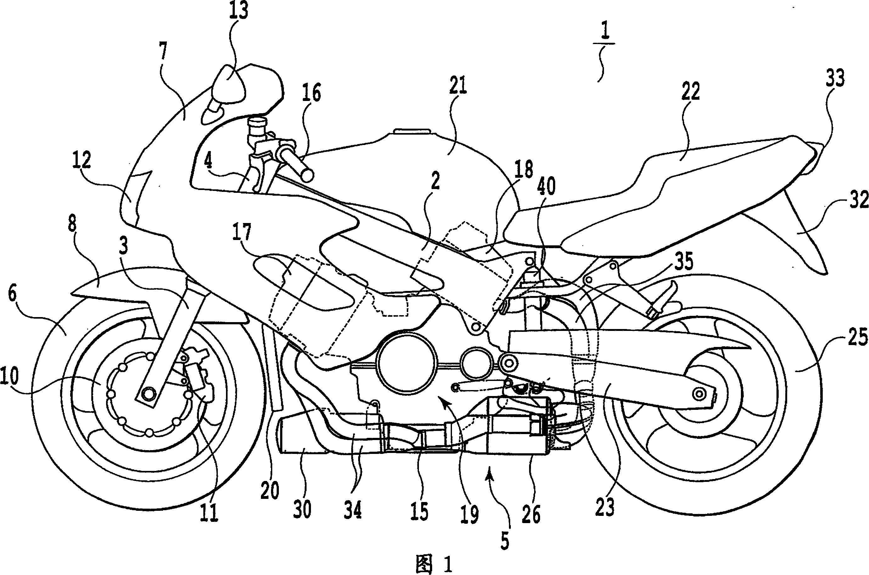
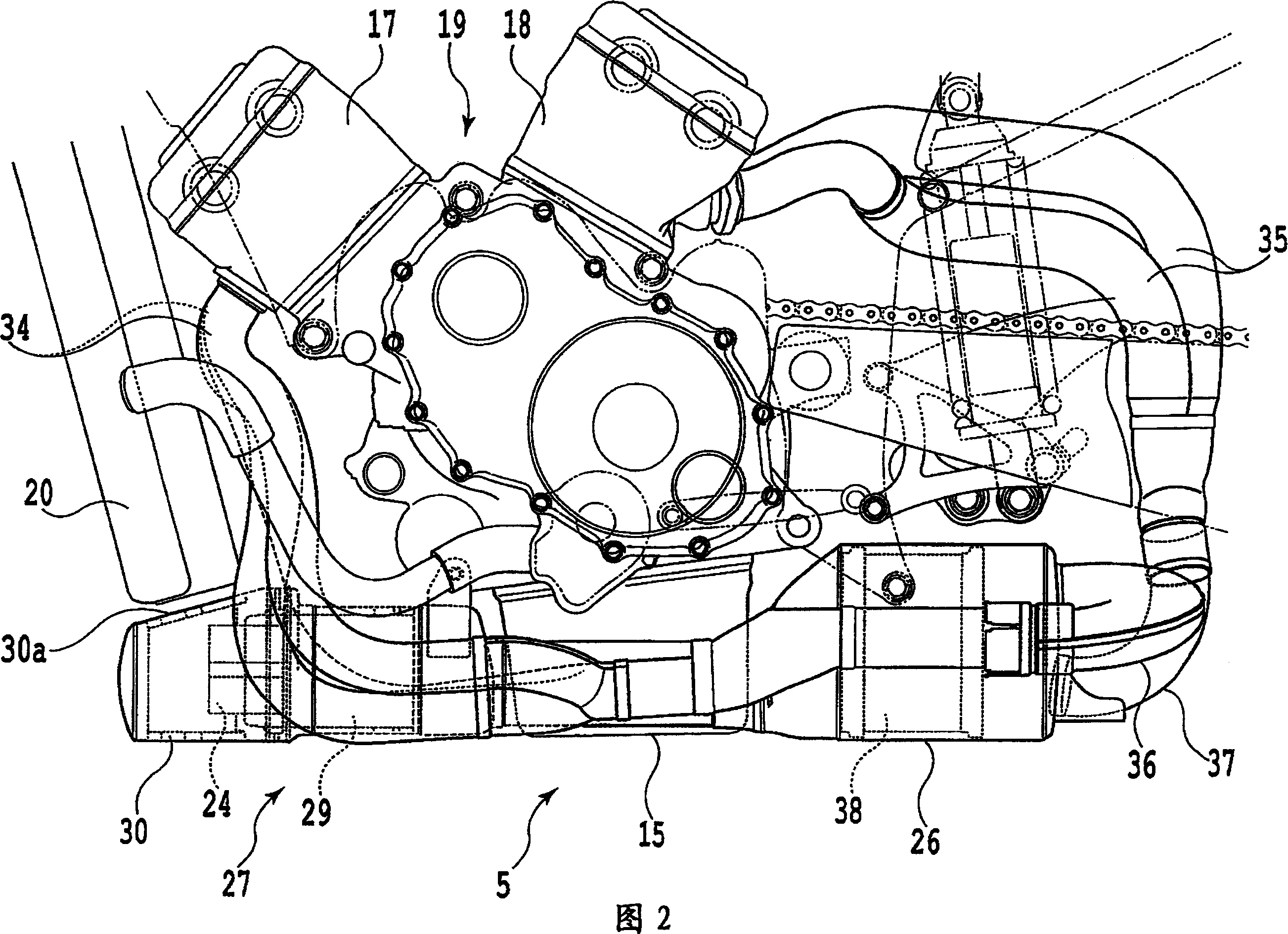
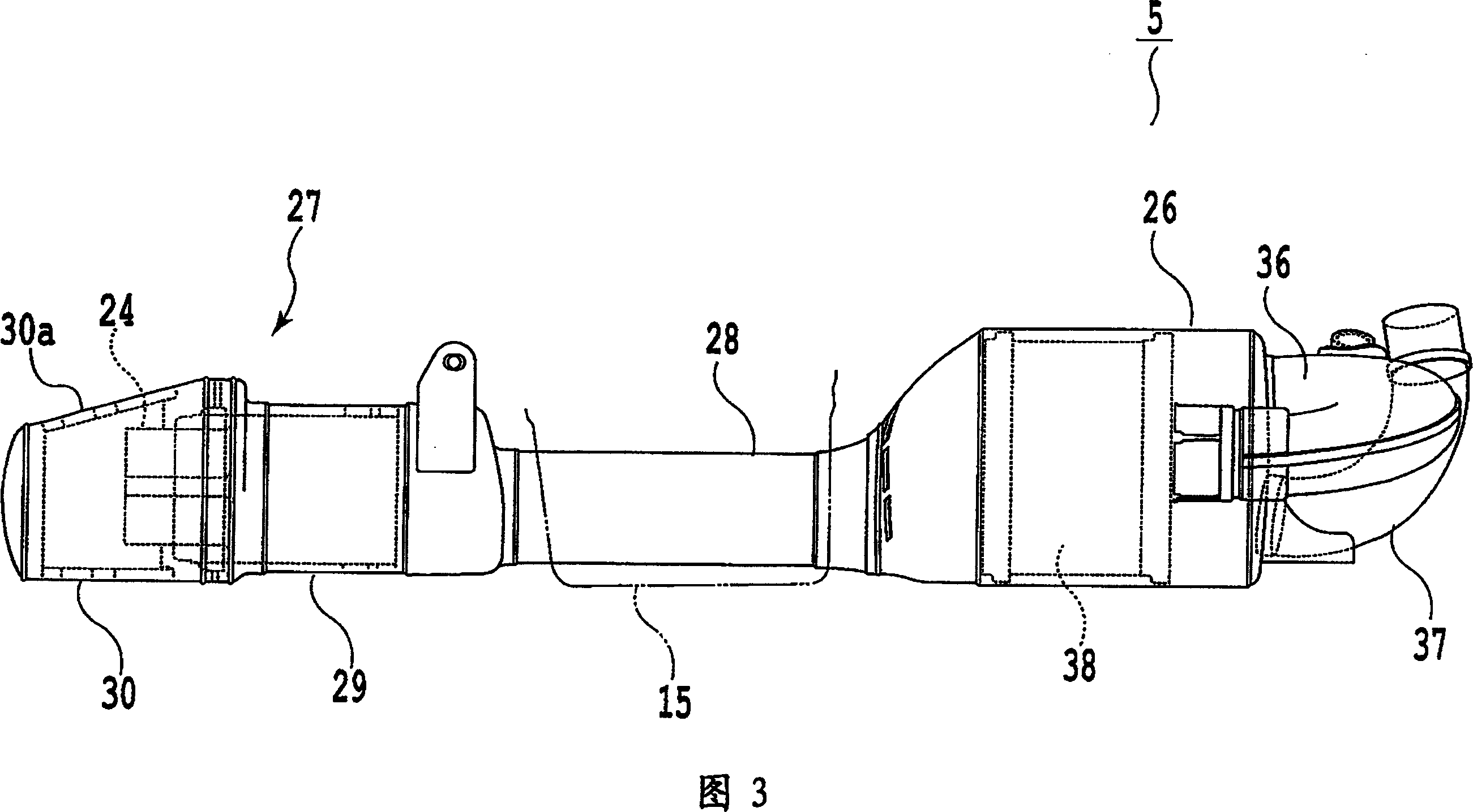
[0041] Fig. 1 is a side view showing a motorcycle having an exhaust device according to a first embodiment of the present invention, Fig. 2 is a side view showing an engine and its periphery of the motorcycle shown in Fig. 1 , and Fig. 3 It is a side view of the first embodiment of the exhaust device of the motorcycle related to the present invention, FIG. 4 is a plan view of the first embodiment of the exhaust device of the motorcycle related to the present invention, and FIG. 5 is The V-V sectional view of the exhaust device of the motorcycle shown in FIG. 4 .
[0042] As shown in FIG. 1 , a motorcycle 1 has a pair of left and right main frames 2 extending diagonally downward from a head pipe 4 , and a front fork 3 is rotatably connected to the head pipe 4 . A handlebar 16 is attached to the upper end of the front fork 3 . On the other hand, a front wheel 6 is rotatably attached to the lower end of the front fork 3 , and a front fender 8 is attached above the front wheel 6 ...
no. 2 Embodiment approach
[0056] 6 is a side view showing a motorcycle engine and its surroundings having a second embodiment of the motorcycle exhaust device according to the present invention. Fig. 7 is a plan view showing a second embodiment of the motorcycle exhaust device according to the present invention.
[0057] In the first embodiment described above, the motorcycle 1 equipped with the horizontal V-type four-cylinder engine 19 has been described. However, as shown in FIGS. 6 and 7, the present invention is equally applicable to an engine 19 equipped with five cylinders of a horizontal V-type in which a cylinder 17 of three cylinders in the front and a cylinder 18 of two cylinders in the rear are crossed into a V shape. two-wheeled motorcycle 1. In this case, as shown in FIG. 6 and FIG. 7 respectively, except that three exhaust pipes 34 are installed on the cylinders 17 of the front three cylinders, and these exhaust pipes 34 are connected to the rear expansion chamber The second embodiment ...
Embodiment approach
[0059] In the above-mentioned embodiment, the two-wheeled motorcycle 1 equipped with a horizontally mounted V-type engine 19 has been described, but the present invention can also be similarly applied to forms other than a horizontally mounted V-type (for example, a vertically mounted V-type motorcycle 1). type, parallel multi-cylinder, etc.) of the two-wheeled motorcycle 1 of the engine 19.
[0060] In the above-mentioned embodiment, as shown in FIG. 4 , the front expansion chamber 27 and the rear expansion chamber 26 arranged in the front and back of the oil pan 15 are connected by the connecting pipe 28, and the above-mentioned connecting pipe 28 is offset to the right side of the vehicle body. However, the connection pipe 28 may also be offset to the left side of the vehicle body. In a word, as long as the connecting pipe 28 is biased on either side of the vehicle body, the above functions and effects can be brought into play.
[0061] In the above-mentioned embodiment, t...
PUM
 Abstract
Description
Claims
Application Information
 - R&D
- Intellectual Property
- Life Sciences
- Materials
- Tech Scout
- Unparalleled Data Quality
- Higher Quality Content
- 60% Fewer Hallucinations
Browse by: Latest US Patents, China's latest patents, Technical Efficacy Thesaurus, Application Domain, Technology Topic, Popular Technical Reports.
© 2025 PatSnap. All rights reserved.Legal|Privacy policy|Modern Slavery Act Transparency Statement|Sitemap|About US| Contact US: help@patsnap.com