Combined cycle method and installation of combustion turbine of burning blast furnace gas

A technology of gas turbine and combined cycle, which is applied in the direction of fuel delivery and charging systems of gas turbine devices, turbines/propulsion devices, etc., to achieve the effect of saving auxiliary systems

A technology of gas turbine and combined cycle, which is applied in the direction of fuel delivery and charging systems of gas turbine devices, turbines/propulsion devices, etc., to achieve the effect of saving auxiliary systems

CN1959084AInactive Publication Date: 2007-05-09INST OF ENGINEERING THERMOPHYSICS - CHINESE ACAD OF SCI

Image

  • Combined cycle method and installation of combustion turbine of burning blast furnace gas

Examples


Embodiment Construction

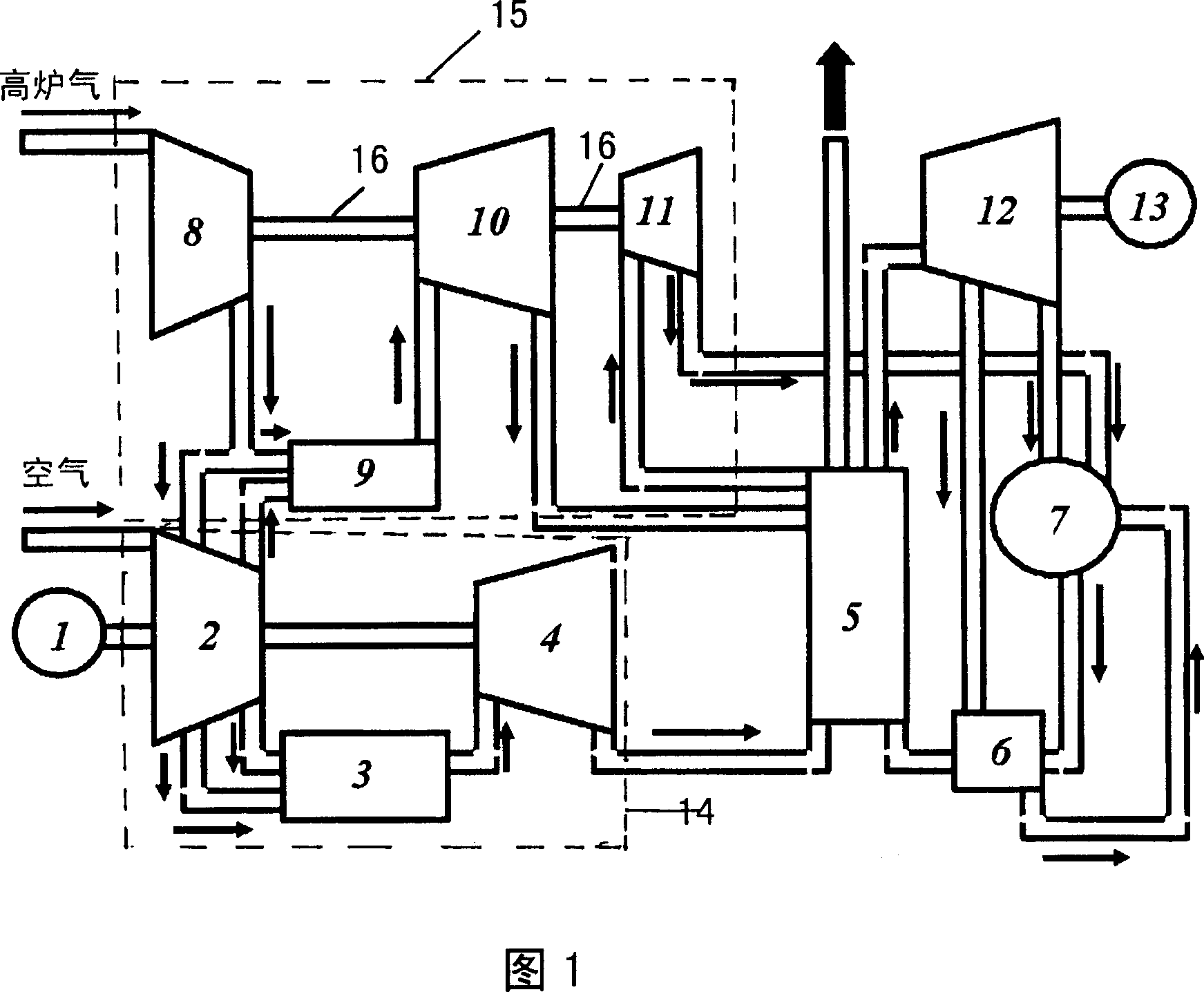
[0015] Using the low calorific value combustor technology of the gas turbine combustor of the Institute of Engineering Thermophysics, Chinese Academy of Sciences, the lower limit of the calorific value of the combustor is locked at 800Kcal / Nm 3 , using the nozzle burning coke oven gas [accounting for 1% of the fuel gas flow] as the on-duty flame, it greatly expands the flameout limit at low load and increases the temperature of the adiabatic flame, so that the combustion efficiency of low calorific value fuel can reach 98% at high load, and at the same time Considering the compressor surge and the passing capacity of the turbine, on the basis of the original number of combustion chambers [main combustion chambers], several combustion chambers [auxiliary combustion chambers] are added, and the gas burned in the auxiliary combustion chambers is led to the low-flow area. The centripetal turbine is connected in series with the first steam turbine formed by the dual-pressure waste h...


PUM


Abstract

A method for unitedly circulating gas turbine utilizing furnace gas includes making cleaned furnace gas be the same pressure grade as air at last stage exit on multistage axial-flow compressor by gas compressor, using said gas as fuel to be inputted to two combustion clamber connected in parallel means and burning said gas with high pressure air provided by multistage axial-flow compressor these for providing a partial power to gas compressor through radial-inward-flow turbine, sending high temperature smoke from said turbine to double-pressure residual-heat boiler for carrying heat exchange these then providing the second partial power to gas compressor through the first steam turbine.

Description

technical field [0001] The invention relates to the technical field of steelmaking, and relates to a combined cycle method and device for burning blast furnace gas and gas turbines. Background technique [0002] The transformation of the heavy-duty natural gas-burning gas turbine into a blast furnace gas-fired unit is now facing a major technical bottleneck. The flow matching of the compressor-combustion chamber-turbine has a structural problem that is difficult to overcome, mainly because of the heat of the fuel gas. The value has reached the minimum limit. Under the original design operating conditions, that is, under the premise of ensuring the same heat output from the combustion chamber, the fuel gas volume is increased several times, that is, the blast furnace gas volume entering the combustion chamber. The increase of these quantities almost reaches the compressor inflow one-third of the combustion chamber. If the unit does not reduce the flow rate of the compressor,...

Claims


Application Information

Patent Timeline
09 May 2007
Publication
CN1959084A
IPC
F02C6/00; F02C7/236
Inventors
聂超群; 徐纲