Nozzle structure of combustion chamber in low heat value of gas turbine, and combustion method

A technology of gas turbine and combustion method, which is applied in the direction of combustion method, combustion chamber, continuous combustion chamber, etc., and can solve the problems such as the increase of flow resistance loss of the combustion chamber

Active Publication Date: 2007-05-09
江苏中国科学院能源动力研究中心 +1
View PDF0 Cites 17 Cited by
  • Summary
  • Abstract
  • Description
  • Claims
  • Application Information

AI Technical Summary

Problems solved by technology

However, enhancing the swirl will increase ...

Method used


Image

  • Nozzle structure of combustion chamber in low heat value of gas turbine, and combustion method
  • Nozzle structure of combustion chamber in low heat value of gas turbine, and combustion method
  • Nozzle structure of combustion chamber in low heat value of gas turbine, and combustion method

Examples


Embodiment Construction

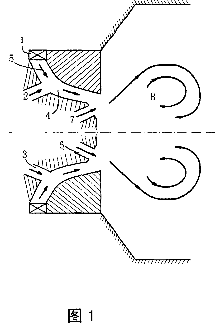
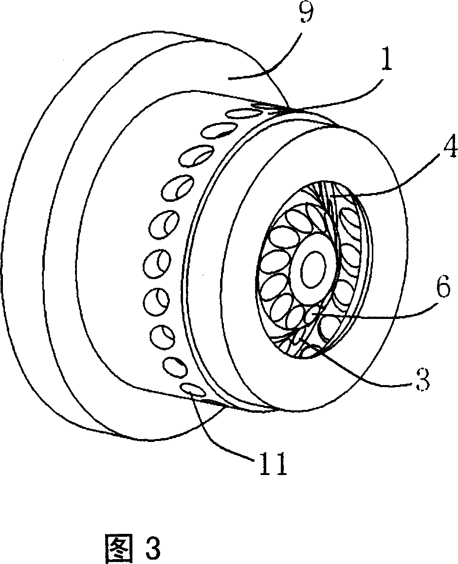
[0031] Fig. 1 is the design method and structural features of the low calorific value nozzle which adopts the combination of diffusion flame and partial premixing in the present invention. This new type of nozzle 9 adopts a radial air swirler 1, and the fuel jets are divided into two rows. The first row of fuel jets 2 directly injects into the swirler channel 4 through the first row of fuel swirl jet holes 3, and the same swirl flow The primary air 5 in the swirler channel 4 forms a rich premixed gas, and the second row of fuel swirl jet holes 6 is located at the outlet of the swirler channel 4, and its jet trajectory is directly injected into the combustion chamber. When the gas turbine works at a low load, the second row of fuel jets 7 forms a pure diffusion flame, which acts as a stable ignition point to maintain stable combustion. When the gas turbine works at high load, the first row of fuel jets 2 is mixed with the primary air 5 in the swirler channel 4, and the second r...


PUM


Abstract

A burning method of nozzle of low heat value combustion chamber on fuel gas turbine applies combustion mode of combining expansion flame with partial premixture to solve problem of non-stable combustion and carbon monoxide residue when low heat value fuel gas is burned.

Description

technical field [0001] The invention relates to the technical field of gas turbines, and relates to a nozzle structure and a combustion method of a low calorific value combustion chamber of a gas turbine. Background technique [0002] Entering the 21st century, the two indicators of rational and effective use of energy and environmental protection measures must meet the requirements. The high energy consumption of large iron and steel enterprises in my country has always been our concern. During the 11th Five-Year Plan period, the country proposed measures to use blast furnace gas and coke oven gas to generate electricity by gas turbines for the purpose of low fuel consumption steel production. In addition, biomass, a new type of energy, has become the fourth largest energy after coal, oil, and natural gas due to its continuous regeneration, environmental friendliness, and ability to suppress global climate anomalies, accounting for about 10% of the world's total energy. 3%...

Claims


Application Information

Patent Timeline
IPC IPC(8): F23R3/58
Inventor 徐纲聂超群俞镔肖云汉黄伟光
Owner 江苏中国科学院能源动力研究中心
Why Eureka
Try Eureka