
Releasable side terminal battery cable connector clamp

A battery and terminal technology, applied in the direction of conductive connection, electrical component connection, connection, etc., can solve problems such as difficult battery components to loosen

Inactive Publication Date: 2007-05-09
BATLOK
View PDF0 Cites 3 Cited by
  • Summary
  • Abstract
  • Description
  • Claims
  • Application Information

AI Technical Summary

Problems solved by technology

Due to the narrow space conditions, it is difficult to perform these or other steps to loosen the battery elements from the side terminals

Method used


Image

  • Releasable side terminal battery cable connector clamp
  • Releasable side terminal battery cable connector clamp
  • Releasable side terminal battery cable connector clamp

Examples


Embodiment Construction

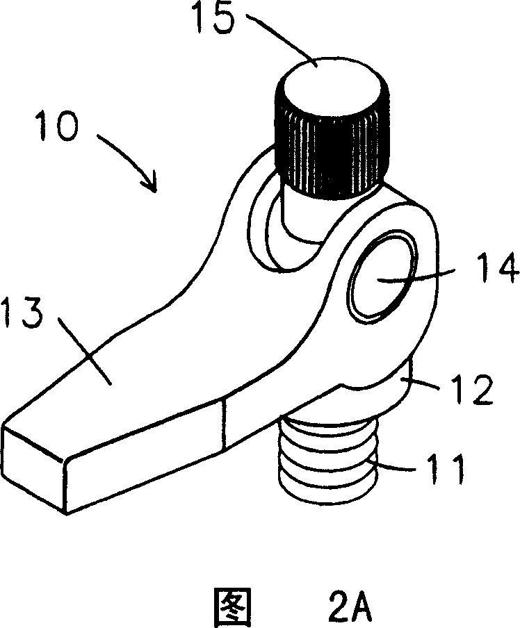
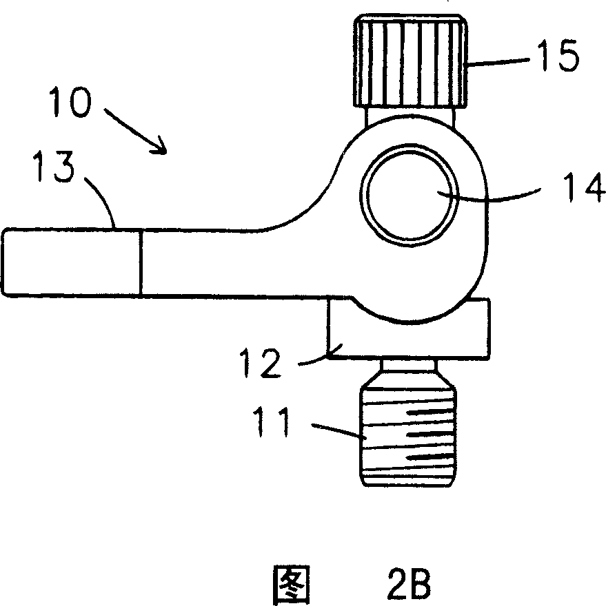
[0023] The description of the preferred embodiment of the invention will be best understood by referring to Figures 1-7 of the drawings, in which like parts are designated by like numerals.

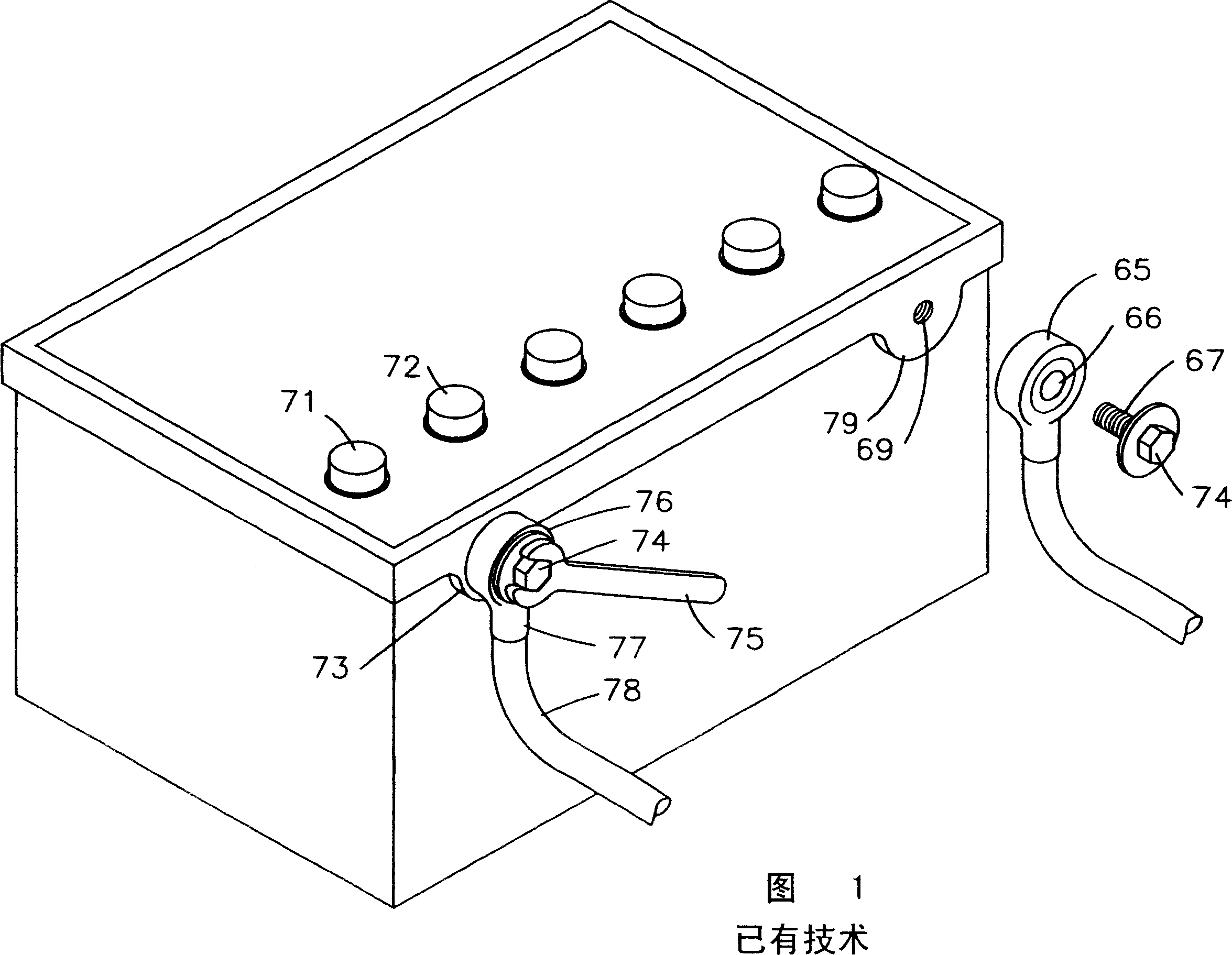
[0024] Referring first to FIG. 1, a typical 12 volt battery 70 having a top positive terminal 71 and a top negative terminal 72 is shown. The accumulator 70 can also have a lateral positive terminal 73 and a corresponding lateral negative terminal 79 . Prior art battery lead terminals 76 have a generally circular distal end or lug 65 with holes 66 for mounting bolts 74 . The bolt 74 has an external thread 67 which engages an internal thread in the bore 69 of the side terminals 73 , 79 . The battery lead terminal or terminal block 76 has a proximal end 77 which is mounted and secured to a battery lead 78 . A wrench can be used to tighten or loosen the bolt 74 so that the battery wire terminal 76 makes firm contact with the side terminals 73, 79 and establishes a wire joint. In use, batt...


PUM


Abstract

A side terminal battery cable converter clamp is provided with a clamp shaft having a distal male threaded end adapted to mate with a female threaded side terminal, said clamp shaft carrying a cam seat, a cammed handle with pin, and a locknut, wherein the cammed handle is operable to frictionally engage and release the distal male threaded shaft end and female threaded side terminal.

Description

field of invention [0001] The present invention relates generally to battery lead clamps and, more particularly, to a battery lead clamp suitable for use on side terminals which facilitates fastening and loosening by hand. Background technique [0002] Those skilled in the art understand that most automobiles, motor vehicles and boats with inboard engines are powered by batteries for starting. A standardized modern battery is a 12-volt battery. Such accumulators have metal terminals for the opposite polarity top side of the battery, to which the terminals of the accumulator wires are fastened. Some 12 volt batteries have side terminals in addition to the top terminals of the battery (or use side terminals instead of the top terminals). The side terminals are conductive plates with internally threaded holes. A standard battery lead terminal (or splice) for the side terminals is connected to the battery lead at one end and the opposite end is a plate with a hole. A bolt is...

Claims


Application Information

Patent Timeline
Patent Type & Authority Applications(China)
IPC IPC(8): H01M2/28H01R4/48H01M50/541
CPCH01R11/282H01R4/5008
Inventor C·M·奥朗日S·埃勒
Owner BATLOK
Learn More