Method for making compression components for rotating blade type compressor

A technology of rotary vane and manufacturing method, applied in rotary piston type machinery, rotary piston type/swing piston type pump components, rotary piston type pump, etc., can solve difficult adjustment of circular blade and annular space tolerance hard plate and inner Ring tolerance, influence on compressor torque, compressor performance degradation, etc

Inactive Publication Date: 2007-05-16
LG ELECTRONICS (TIANJIN) APPLIANCES CO LTD
View PDF0 Cites 0 Cited by
  • Summary
  • Abstract
  • Description
  • Claims
  • Application Information

AI Technical Summary

Problems solved by technology

[0007] The circular vane is integrally formed under the hard plate of the rotating vane, and there is a disadvantage that it is very difficult to grind the underside of the hard plate that is in contact with the inner ring and the upper surface of the cylinder.
[0008] The inner ring is integrally formed into the annular space of the cylinder, and there is a disadvantage that it is very difficult to grind the upper surface of the inner side of the annular space that contacts the lower surface of the circular blade of the rotating blade.
[0009] Difficult to adjust tolerances between circular vanes and annulus and between hard plate and inner ring when combining rotating vanes and cylinders
[0010] Since the bottom of the hard plate and the inner top of the annular space are not sufficiently ground, friction loss and gas leakage will occur on the contact surface when the compressor is running, and the performance of the compressor will drop significantly.
[0011] Since the rotating vane, cylinder and sub-support are made of castings, the weight is heavy, which affects the torque of the compressor, so precision machining is required in addition, which reduces productivity and increases processing costs.

Method used


Image

  • Method for making compression components for rotating blade type compressor
  • Method for making compression components for rotating blade type compressor
  • Method for making compression components for rotating blade type compressor

Examples


Embodiment Construction

[0039]The present invention is described in further detail below in conjunction with the accompanying drawings and specific embodiments:

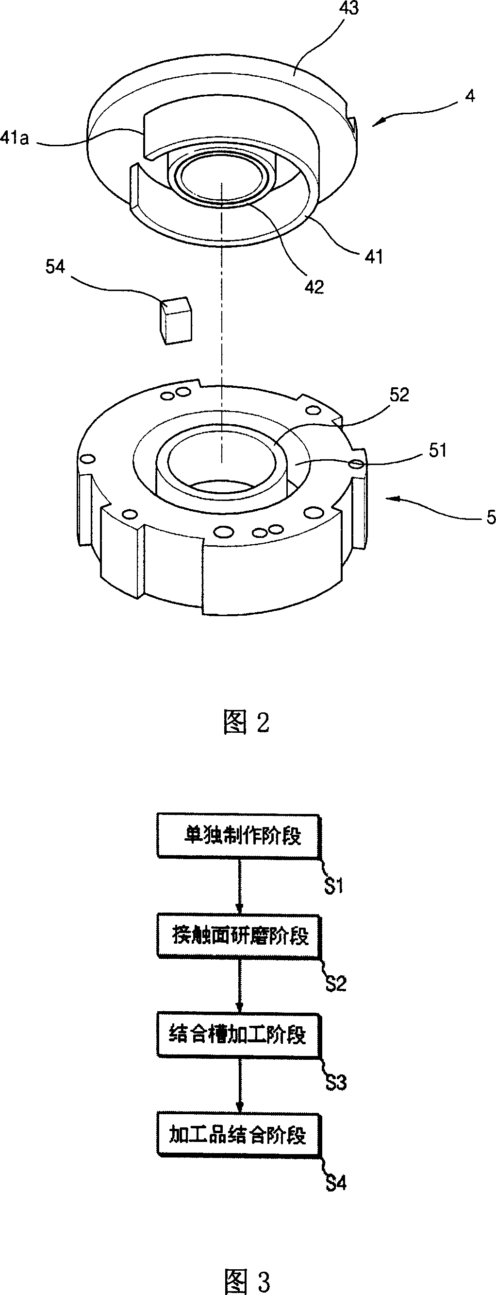
[0040] As shown in FIG. 3 , the manufacturing method of the compression part of the rotary vane compressor of the present invention includes a separate manufacturing stage S1 for separately manufacturing the components that need to be ground, and a contact surface grinding stage S2 for grinding the contact surfaces of the separately manufactured components, The joining groove processing stage S3 in which joining grooves are machined on the components to be joined is constituted by the processing product joining stage S4 in which the components are joined to each other through the joining grooves.

[0041] The separate production stage S1 refers to the stage of separately producing the circular blade and the hard plate of the rotating blade, and separately producing the cylinder with the annular space and the inner ring.

[0042] In the abov...


PUM


Abstract

The compressing method for a rotary vane type compressor comprises the stage of making hard plates, round vanes, cylinders, and separate making of each inside rings, the contact grinding stage of the part under the hard plate and the round vane, above the inside of the ring space and inner ring, the jointing groove processing stage under the hard plate and above the inside of the ring space, and the combining stage of processed part by combining the top of the round vanes in the combining groove on the hard plate and combining the bottom of the inner rings in the combining groove of the ring space. While making the grinding process easier for the contact phase of the rotary vanes and other components touched with it, it can easily adjust the tolerance in the combining process.

Description

technical field [0001] The present invention relates to a rotary vane compressor, in particular, to a method for manufacturing a compression part of a rotary vane compressor which can facilitate the grinding process of the contact surface of the rotary vane and the contact surface of other components contacting the same. Background technique [0002] Generally, as shown in FIG. 1 , a rotary vane compressor includes a rotary shaft 6 , a drive part D, and a compression part P. The rotating shaft 6 is vertically installed inside a casing 1 where the refrigerant is sucked through the lower side suction pipe 11 and then discharged through the upper side discharge pipe 12, and is supported on the main bracket 7 and the sub bracket 7a for rotation, and has an eccentric portion 6a; D is composed of the rotor 3 and the stator 2 which are arranged on the upper part of the rotating shaft 6 to drive the rotating shaft 6 according to the conduction power; The circular vane 41 of the rot...

Claims


Application Information

Patent Timeline
Patent Type & Authority Applications(China)
IPC IPC(8): F04C29/00F04C18/00
Inventor 刘东原黄善雄
Owner LG ELECTRONICS (TIANJIN) APPLIANCES CO LTD
Why Eureka
Try Eureka