
Air conditioner

An air conditioner, air purification technology, applied in the direction of air conditioning system, high-efficiency regulation technology, space heating and ventilation details, etc., can solve the method of undisclosed control, undisclosed, no mention of improving dust collection ability, removal, etc. question

Inactive Publication Date: 2007-05-16
HITACHI APPLIANCES INC
View PDF2 Cites 11 Cited by
  • Summary
  • Abstract
  • Description
  • Claims
  • Application Information

AI Technical Summary

Problems solved by technology

[0009] However, in the air conditioner disclosed in Patent Document 1, the up and down air deflectors for appropriately controlling the air outlet during the operation of the vacuum cleaner have not been fully considered.
That is, when electric vacuuming is required, it is desirable to efficiently and quickly remove dust such as pollen floating in the room from the entire room without hindering the comfort of people living in the room, and to remove pollen that enters the room through natural ventilation. etc. before the dust falls to the floor plate, but Patent Document 1 does not disclose a method to properly handle these situations and control the up and down wind direction plate
Also, when there is no one in the room, it is desirable to fly up dust such as pollen that has landed on the floor and actively remove it, but Patent Document 1 does not disclose a method for properly dealing with these situations and controlling them.
[0010] Although the air purifier of Patent Document 2 discloses the method of using the human sensor to prevent the wind from blowing in the direction of the person, it does not mention improving the dust collection ability, removing dust such as pollen falling on the floor surface, and changing the air due to natural replacement. Pollen and other aspects of air invasion from the outside

Method used


Image

  • Air conditioner
  • Air conditioner
  • Air conditioner

Examples


Embodiment Construction

[0044] An embodiment of the air conditioner of the present invention will be described below with reference to the accompanying drawings.

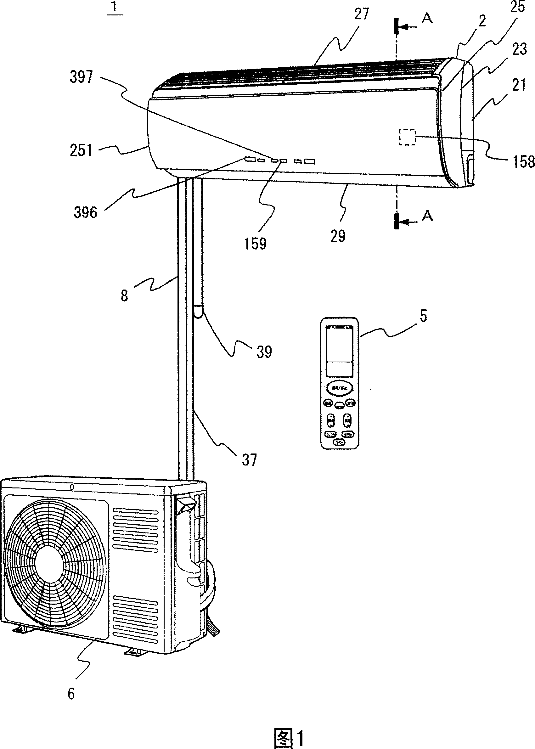
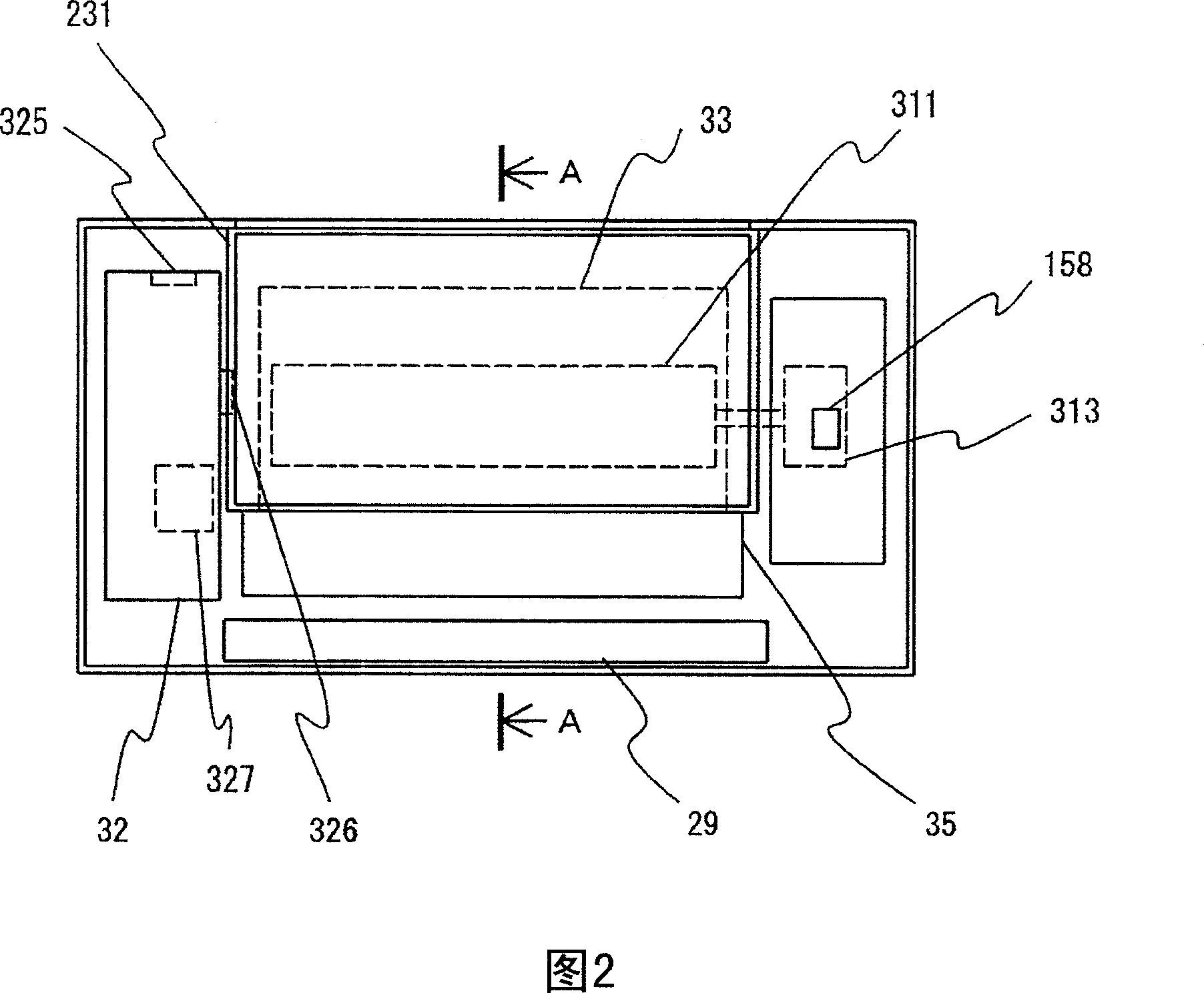
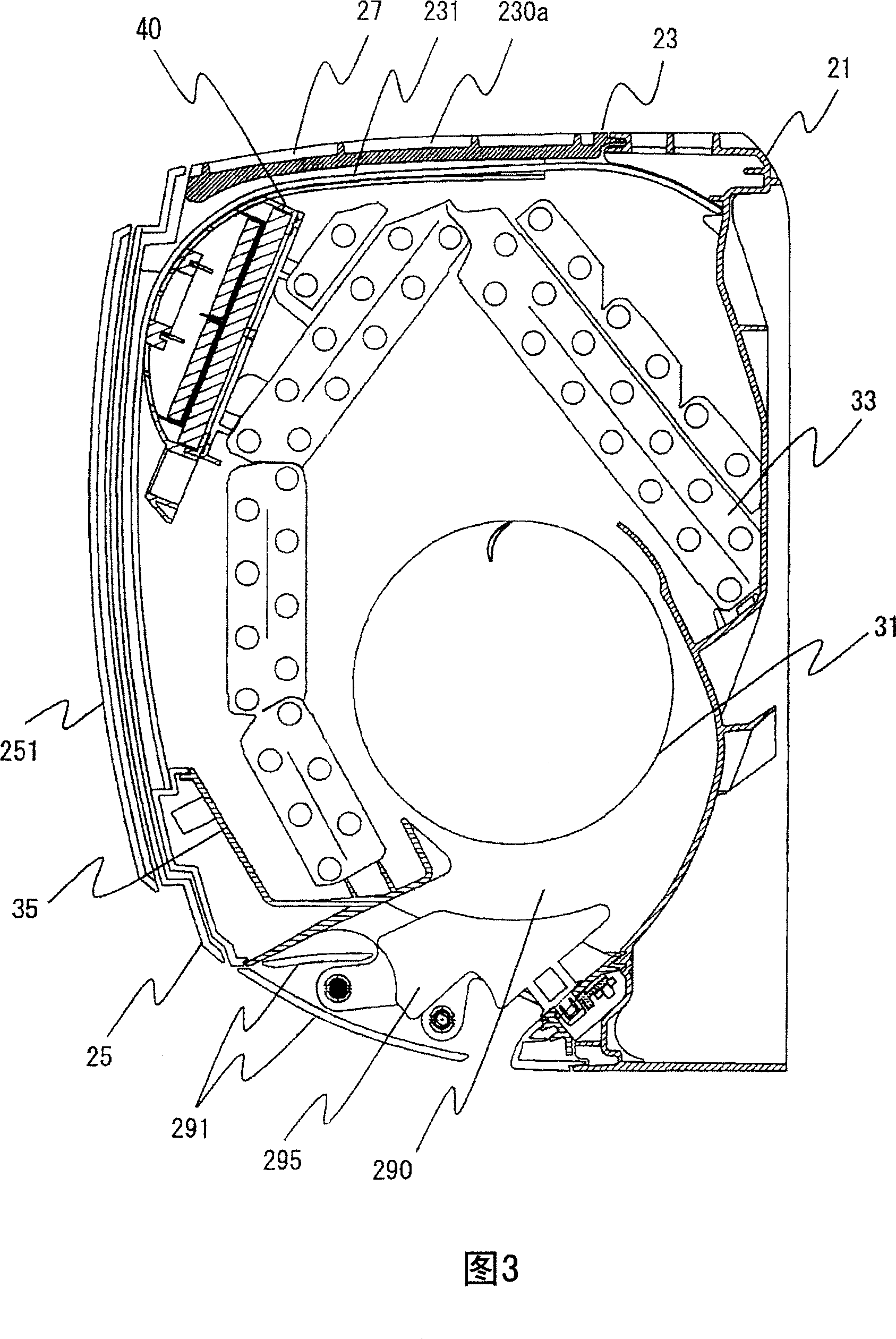
[0045] First, the overall structure of the air conditioner will be described with reference to FIGS. 1 to 4 . Fig. 1 is a perspective view showing the structure of an air conditioner according to an embodiment of the present invention, Fig. 2 is an explanatory view of the internal structure after the panel of the indoor unit of Fig. 1 is removed, Fig. 3 is a sectional view along line A-A of Fig. 2 , Fig. 4 is a perspective view illustrating opening and closing of a movable panel of the indoor unit of Fig. 1 .

[0046] The air conditioner 1 connects the indoor unit 2 and the outdoor unit 6 with a connecting pipe 8, and is configured to adjust indoor air. The indoor unit 2 is equipped with: a housing 21 with an air inlet 27 on the top and an air outlet 28 on the bottom; a movable plate 251 provided to open and close at least a part of the a...


PUM


Abstract

An air conditioner is provided by the invention, which can effectively collect the dust in the indoor and fast reduce the dust concentration without disturbing the comfort for the people in the indoor, wherein an air absorption inlet (27) is arranged thereon, meanwhile, an air blowing exit (28) at the bottom. In order to open and close at least one part of the air absorption inlet, a movable plate (251) is disposed, wherein an up and down wind direction plate (291) at the air blowing exit, an indoor heat exchanger (33) at the absorption side of the blowing fan (311), and an electric dust absorption air cleaning unit (40) between the air absorption inlet and the indoor heat exchanger. The air conditioner includes a control device to make the movable plate open to be controlled when in cold blast operation or the warm wind operation, meanwhile, the movable plate is closed when in air cleaning operation to run the electric dust absorption air cleaning unit, to make the up and down wind direction plate composed of the up field angle in the level or the maximum.

Description

technical field [0001] The invention relates to an air conditioner, and is especially suitable for the air conditioner equipped with an electric dust-absorbing air cleaning unit. Background technique [0002] In late years, people suffering from hay fever with mass scattering of cedar pollen increases. Hay fever is caused by an allergic reaction to pollen as an allergen and is characterized by sneezing, runny nose and itchy eyes. As the allergen of hay fever, cedar pollen can be mentioned above all. In addition, hinoki pollen, which is similar in nature and state to cedar pollen, can also be cited. Since the pollen is scattered at different times, it is necessary to pay attention to pollen for a long time disease. [0003] In addition to pollen, there is an increase in harmful microscopic animals indoors due to house dust and tobacco smoke associated with living, as well as the breeding of ticks due to the perennial comfort of indoor environments such as keeping pets indoo...

Claims


Application Information

Patent Timeline
IPC IPC(8): F24F11/02F24F1/00F24F13/28
CPCY02B30/70F24F1/0011F24F11/79F24F13/10F24F2120/10F24F2110/64F24F1/0076F24F11/65F24F11/0001F24F2110/65
Inventor 滨田进茂木喜和井本勉大塚厚
Owner HITACHI APPLIANCES INC
Learn More