
Led spotlight having funnel-shaped lens

A LED spotlight, transparent technology, applied in the direction of light source, lighting and heating equipment, electric solid-state devices, etc., can solve problems such as difficulties

Inactive Publication Date: 2007-05-16
TRIDONIC OPTOELECTRONICS GMBH
View PDF1 Cites 17 Cited by
  • Summary
  • Abstract
  • Description
  • Claims
  • Application Information

AI Technical Summary

Problems solved by technology

For refractive lenses, especially in the case of fine emitting LEDs, difficulties arise in mixing blue light with converted yellow light to emit uniform white light over the entire emission range

Method used


Image

  • Led spotlight having funnel-shaped lens
  • Led spotlight having funnel-shaped lens
  • Led spotlight having funnel-shaped lens

Examples


Embodiment Construction

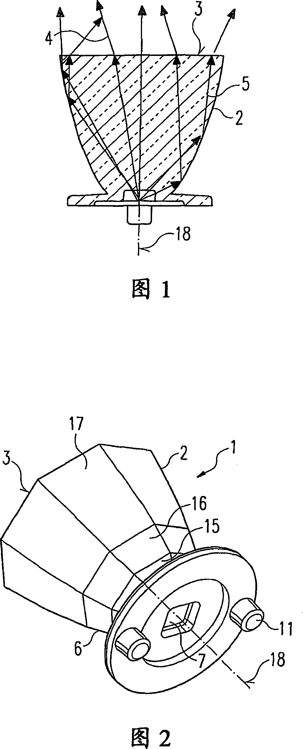
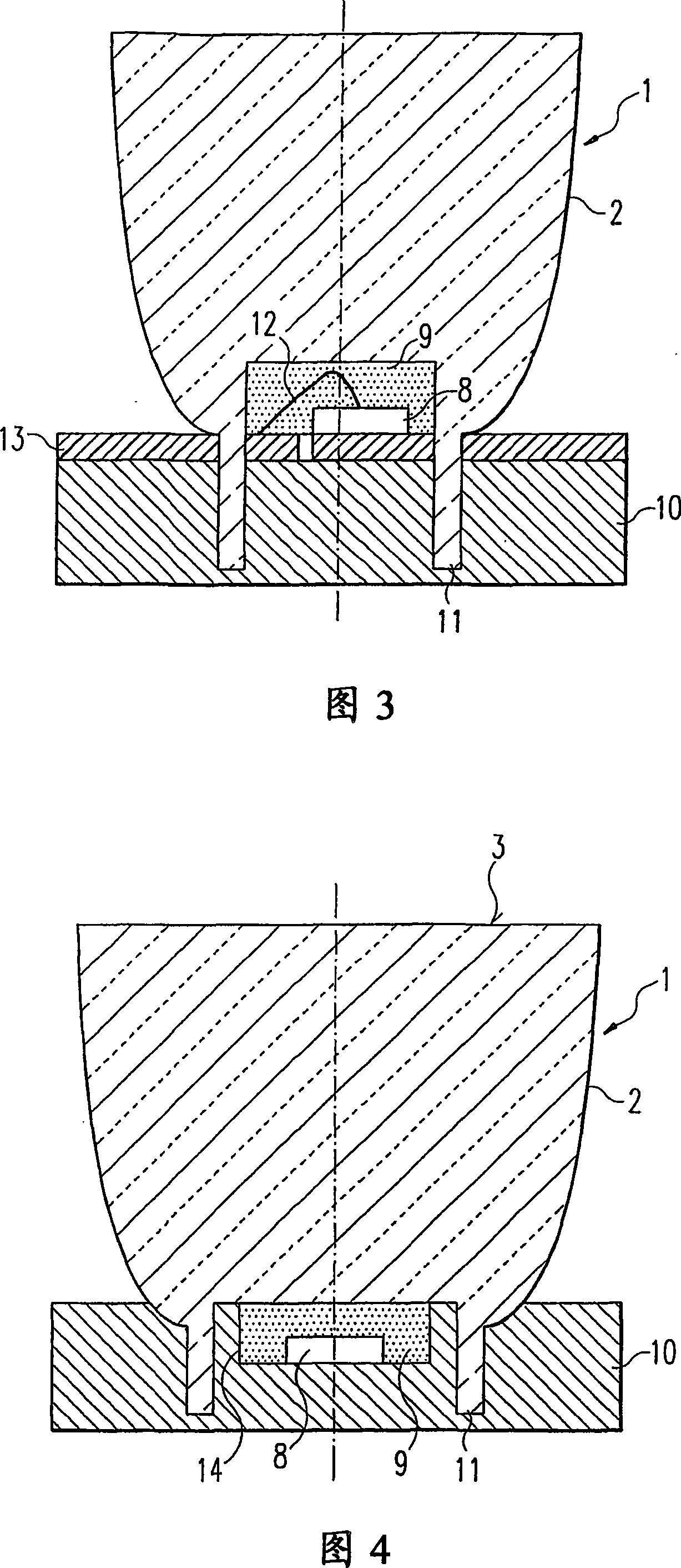
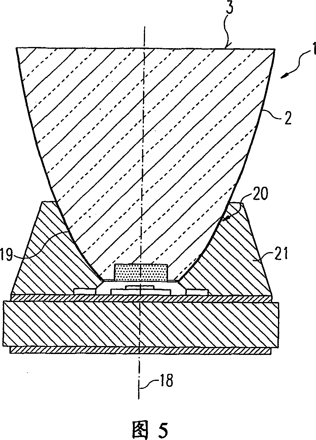
[0040] As shown in Figure 1, according to the present invention there is provided an LED spotlight having a funnel-shaped lens in the form of a conical optical system 1 of substantially transparent solid material having side walls 2 and the exit surface 3 perpendicular to the axis of symmetry of the conical optical system 1. The material of the conical optical system may have a refractive index of, for example, 1.4-1.6, especially 1.5-1.55.

[0041] In the boundary layer from the conical optics to the surrounding air, incident light from the inside is totally reflected so that light does not exit on the side walls of the conical optics. And since the light is actually incident on the exit surface of the conical optical system at a more oblique angle, the light is not reflected but merely refracted away from the normal to the exit surface.

[0042] Through the acute angle of the outer surface of the conical optical system with respect to its axis of symmetry, it is ensured tha...


PUM


Abstract

The invention discloses an LED spotlight which comprises an arrangement with at least one LED above which a color conversion substance is disposed and a lens system. Said lens system is produced from a substantially transparent material and deviates incident light by total reflection from the LED arrangement in the direction of an exit surface. The base of the conical lens system can have a polygonal shape. The outer wall of the conical lens system can be provided with planar facets in at least some sections. The color conversion material can be provided above the LED arrangement as a cuboid structure.

Description

technical field [0001] The invention relates to an LED spotlight. Background technique [0002] The background of the invention is the field of light emitting diodes (LEDs), in particular "white" light emitting diodes (LEDs). According to the state of the art, for the use of LEDs to produce white light, colored, in particular blue, light is produced using color conversion or by mixing light components from LEDs of different colors. For example, white light can be produced by mixing blue light produced by an LED chip with yellow light produced by a portion of the blue light as it passes through a color converting material surrounding the LED. [0003] Due to the characteristics of the color conversion material and some technical limitations in the production process of the LED, areas of different colors are often produced in the color conversion layer arranged above the LED, and these different color areas cause uneven colors through its imaging. distributed. This phenomen...

Claims


Application Information

Patent Timeline
IPC IPC(8): H01L33/00F21K7/00F21K99/00H01L33/54H01L33/58H01L33/60
CPCH01L33/54H01L33/58H01L33/60H01L2924/0002H01L2924/00
Inventor 汉斯·霍斯西普夫斯蒂芬·塔施彼得·帕希勒
Owner TRIDONIC OPTOELECTRONICS GMBH
Learn More