Copper tube end sealing method
A copper tube and tube end technology, applied in the field of tube end sealing of copper tubes, can solve the problems of reduced secondary workability and the like
- Summary
- Abstract
- Description
- Claims
- Application Information
AI Technical Summary
Problems solved by technology
Method used
Image

Examples
Embodiment 1
[0017] Embodiment 1, comparative example 1
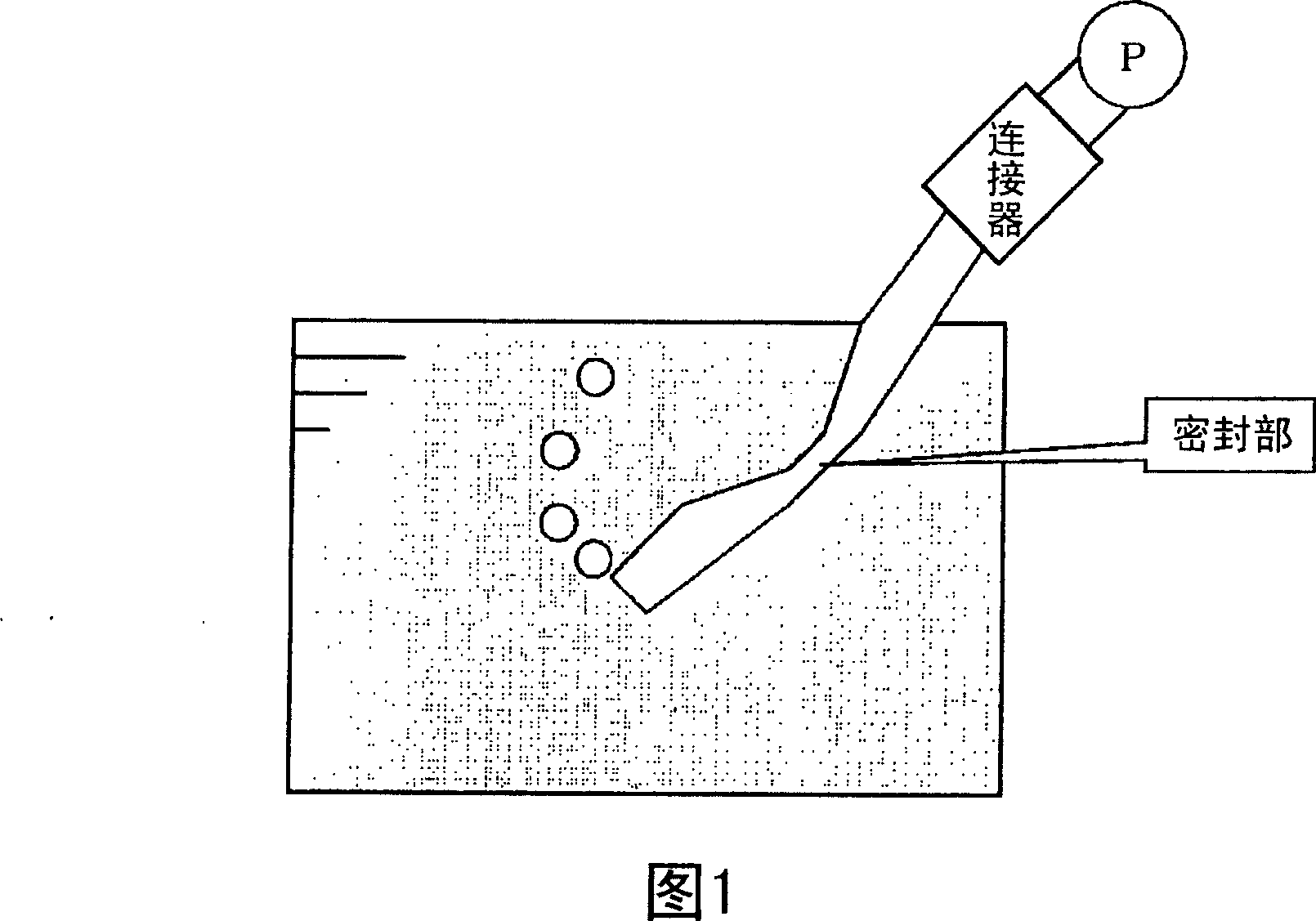
[0018] Seal the end of the ACR copper pipe (smooth copper pipe) with an outer diameter of 8mm (thickness: 0.30mm) by the following methods (A) and (B). As shown in Figure 1, put the sealed side into the water and connect Connect the opposite side to the pump, and use the pump to input air into the pipe at a pressure of 0.8 MPa to perform an airtightness maintenance evaluation test. At this time, no air bubbles from the sealing side were observed in the sealing of the method (A). , but it was confirmed that air bubbles were generated from the sealing side in the sealing of the method (B). In addition, after annealing, when the inside of the LWC tube of the ACR copper tube is replaced with an inert gas or dry oxygen, the purge gas pressure (Pa ji gas pressure) is at most about 0.6 MPa, and a pressure slightly higher than this pressure is used as the test pressure.
[0019] Method (A): Place a support member with a width of 5mm (5mm ...
Embodiment 2
[0021] Embodiment 2, comparative example 2
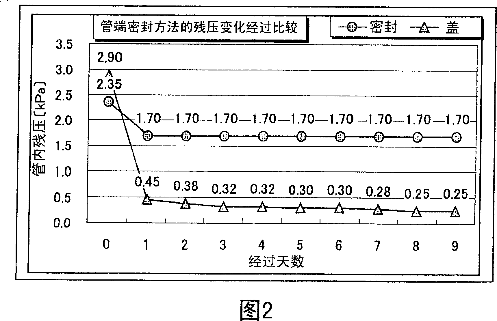
[0022] With the method (C) shown below and the method (B) above, one end of the LWC tube of the ACR copper tube (copper tube with a groove on the inner surface) with an outer diameter of 8 mm (thickness: 0.30 mm) is sealed, and the connector is passed Install a pressure gauge near the sealing part, and after replacing the inside of the tube with an inert gas with a purge gas pressure of 0.6MPa, use the same method to seal the other end, and use the pressure gauge to measure the residual pressure change in the tube through The results of the comparison are shown in Fig. 2. In the method (C) of sealing (the sealing in Fig. 2), the residual pressure in the tube is kept at a high pressure and kept constant. In contrast, in the method (B) of sealing ( In FIG. 2 , it is the cap), it was confirmed that the residual pressure in the tube gradually decreased with the passage of days. In addition, in both methods, although the pressure is see...
PUM
| Property | Measurement | Unit |
|---|---|---|
| Diameter | aaaaa | aaaaa |
| Outer diameter | aaaaa | aaaaa |
| Thickness | aaaaa | aaaaa |
Abstract
Description
Claims
Application Information
 - Generate Ideas
- Intellectual Property
- Life Sciences
- Materials
- Tech Scout
- Unparalleled Data Quality
- Higher Quality Content
- 60% Fewer Hallucinations
Browse by: Latest US Patents, China's latest patents, Technical Efficacy Thesaurus, Application Domain, Technology Topic, Popular Technical Reports.
© 2025 PatSnap. All rights reserved.Legal|Privacy policy|Modern Slavery Act Transparency Statement|Sitemap|About US| Contact US: help@patsnap.com