Water cooling device for printing machine cooling roll

A water-cooling device and cooling roller technology, applied in printing presses, rotary printing presses, rotary flattening presses, etc., can solve the problems of slow water circulation of cooling rollers, large resistance of cooling rollers, affecting feeding tension, etc., and achieve fast circulation speed. , flexible rotation, improve the effect of cooling effect

Inactive Publication Date: 2007-05-23
NINGBO XINDA PRINTING MACHINERY
View PDF1 Cites 9 Cited by
  • Summary
  • Abstract
  • Description
  • Claims
  • Application Information

AI Technical Summary

Problems solved by technology

[0002] Most of the current printing machines such as high-speed gravure printing machines, flexographic printing machines, and dry laminating machines use self-overflow cooling rolls. In practice, it has been shown that the original self-overflow cooling rolls still have many shortcomings, such as The cooling roller is relatively heavy, and one end is heavy and the other end is light, which will greatly affect the feeding tension, so it is not suitable for high-speed machines with a printing speed higher than 200 m / min; the cooling roller originally uses a spiral joint to enter and exit water, and the cooling roller has a large resistance. It is not suitable for printing machines with high printing speed; the water circulation of the cooling roller originally used for the cooling roller is relatively slow, and the cooling effect is poor, which is not conducive to production

Method used


Image

  • Water cooling device for printing machine cooling roll
  • Water cooling device for printing machine cooling roll
  • Water cooling device for printing machine cooling roll

Examples


Embodiment Construction

[0018] The present invention will be further described in detail below in conjunction with the accompanying drawings and embodiments.

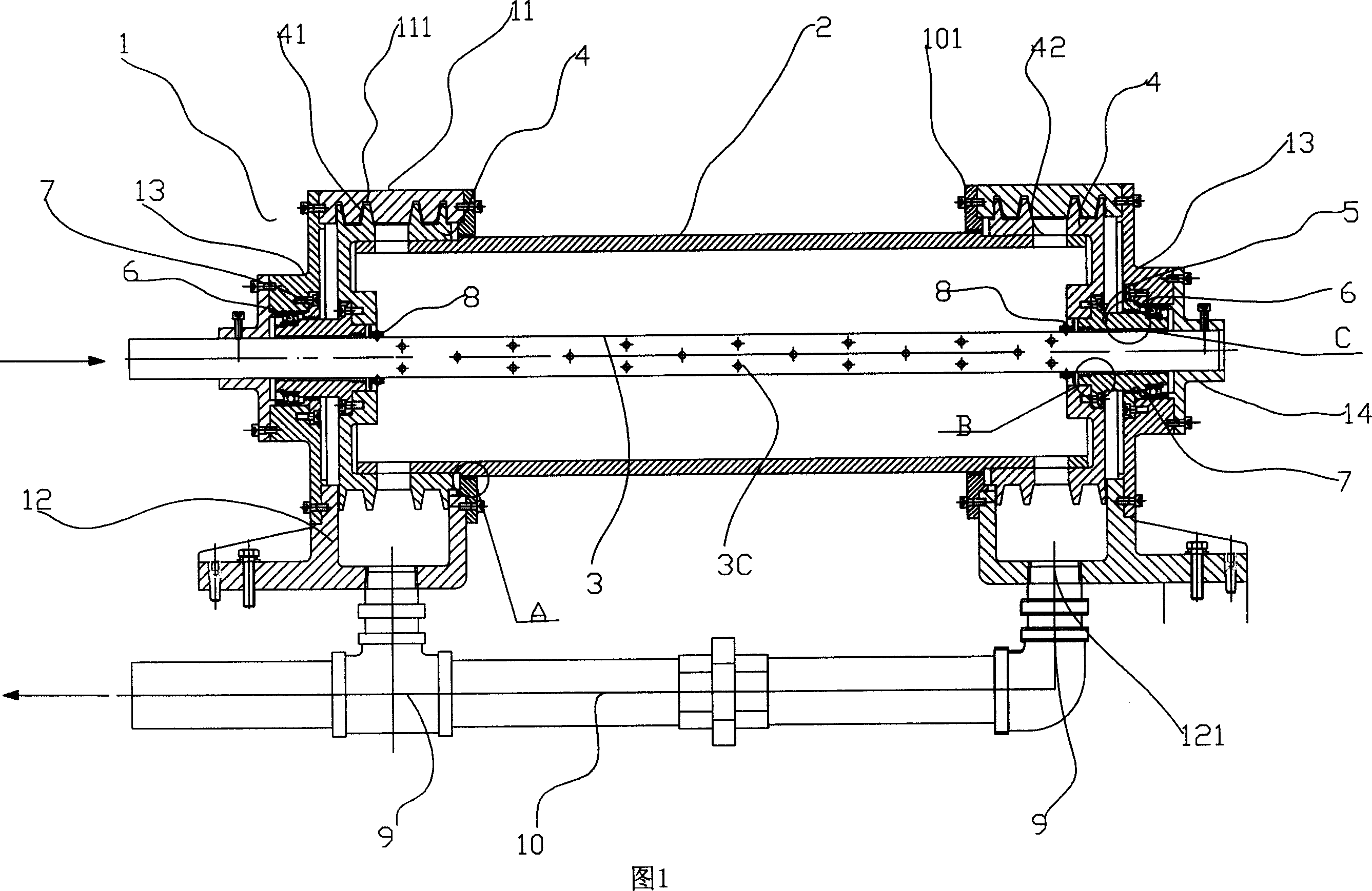
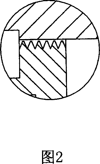
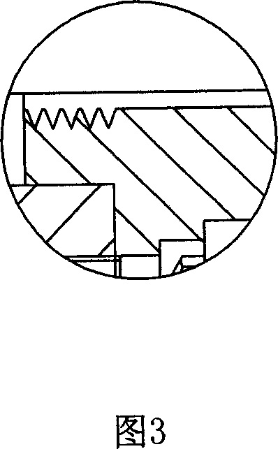
[0019] As shown in Fig. 1-4, the water cooling device of the cooling roller of the printing machine includes a main body frame, a cooling roller 2, a water inlet pipe 3, a water return pipe 10, a water throwing wheel 4, a bearing 6, a bearing seat 5, a sealing ring 8 and other main components. Components, wherein the box body 1 is composed of two sets of upper box body 11 and lower box body 12. After being fixed as a load-bearing body, it is erected on the plane of the printed wall board. The outer end faces of both sides of the box body 1 are connected and fixed with outer end covers 13 by bolts. . There are cooling rollers 2 that can rotate flexibly in the box body 1. The water throwing wheels 4 are set on both ends of the cooling roller 2, one on the left and one on the left. Each water throwing wheel 4 has four convex gear rings 41, two on...


PUM


Abstract

The invention relates to a water cooler of cooling roller of printer, wherein it comprises that: carrier frame, cooling roller, water inlet tube, and reflux tube; the frame via bearing and bearing base is mounted with rotational cooling roller; the water inlet tube with injection holes is through into cooling roller; and the reflux tube is connected to out space. The invention is characterized in that: two ends of cooling roller are sheathed with water wheel through to the holes of cooling roller; the outer surface of water wheel is shaped with convex tooth ring; the inner surface of frame is shaped with annular groove to contain the outer convex tooth ring; the box is through to the reflux tube. The invention has better cooling effect, simple structure and easy installment, to be used on high-speed printer.

Description

technical field [0001] The invention relates to a water cooling device for cooling rollers of printing machines. Background technique [0002] Most of the current printing machines such as high-speed gravure printing machines, flexographic printing machines, and dry laminating machines use self-overflow cooling rolls. In practice, it has been shown that the original self-overflow cooling rolls still have many shortcomings, such as The cooling roller is relatively heavy, and one end is heavy and the other end is light, which will greatly affect the feeding tension, so it is not suitable for high-speed machines with a printing speed higher than 200 m / min; the cooling roller originally uses a spiral joint to enter and exit water, and the cooling roller has a large resistance. It is not suitable for printing machines with high printing speed; the water circulation of the cooling roller originally used for the cooling roller is relatively slow, and the cooling effect is poor, whi...

Claims


Application Information

Patent Timeline
Patent Type & Authority Applications(China)
IPC IPC(8): B41F13/22B41F3/52
Inventor 蔡康强
Owner NINGBO XINDA PRINTING MACHINERY
Why Eureka
Try Eureka