

Assembling type wood door leaf
A solid wood door, assembled technology, applied in the field of wooden doors, can solve problems such as the inability to stand the door, the transom or the replacement of the door blocking plate, etc.
- Summary
- Abstract
- Description
- Claims
- Application Information
AI Technical Summary
Problems solved by technology
Method used
Image

Examples
Embodiment Construction
[0023] Now in conjunction with the accompanying drawings, a preferred embodiment of the assembled solid wood door leaf of the present invention will be described.
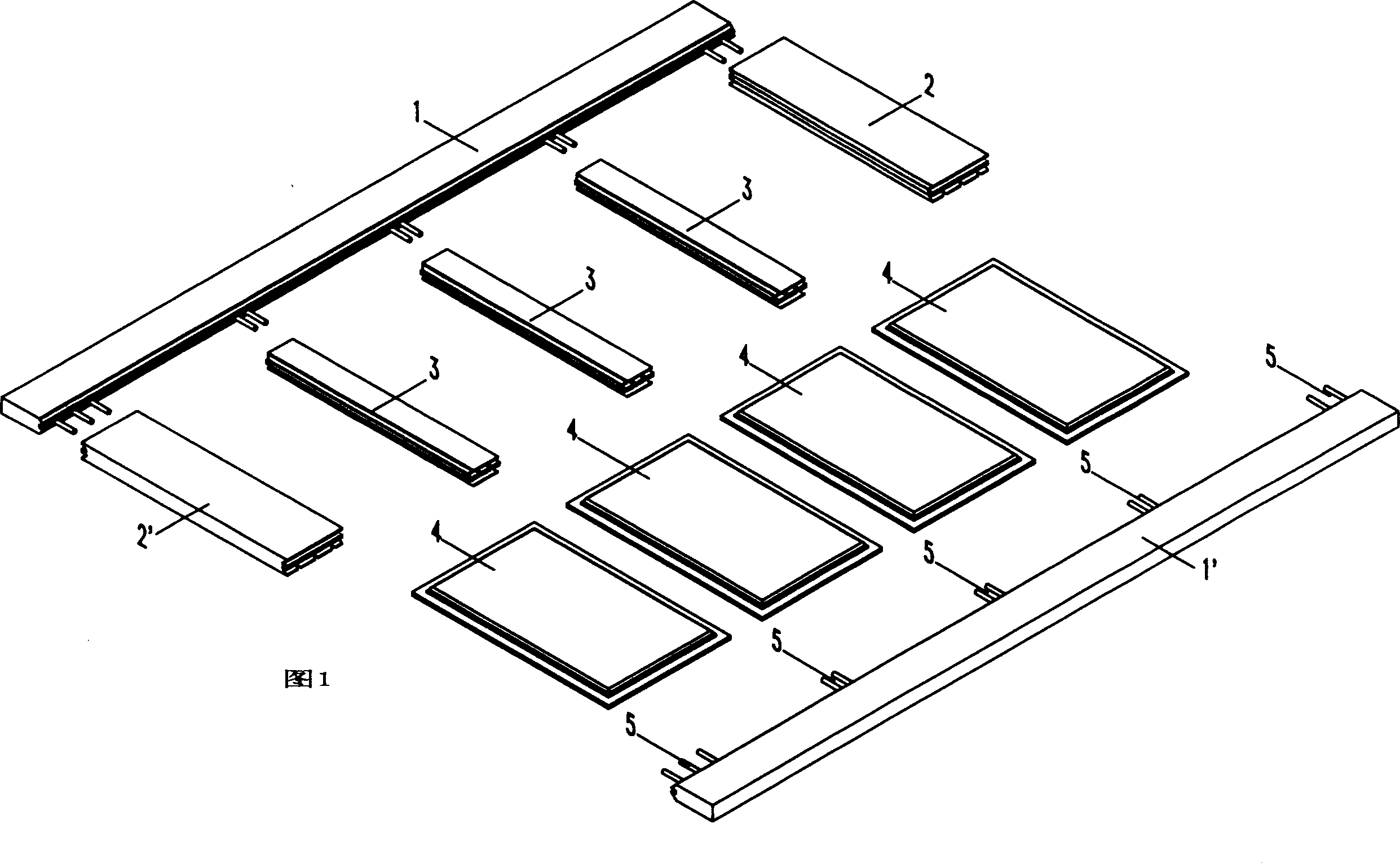
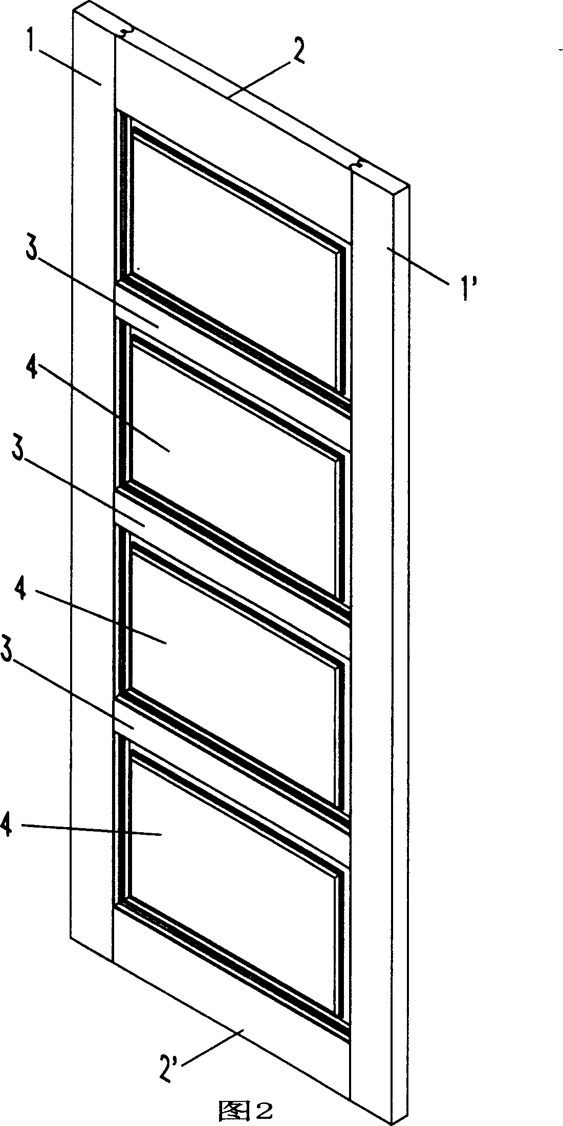
[0024] As shown in Figure 1, the assembled solid wood door leaf consists of a left door stand 1, a right door stand 1', an upper crosspiece 2, a lower crosspiece 2', three middle crosspieces 3, four door blocking plates 4 and Twenty-four wooden pegs consist of 5. Left door stand 1, right door stand 1 ', upper crosspiece 2, lower crosspiece 2', each middle crosspiece 3 and each door blocking plate 4 have carried out fully-sealed paint respectively, so that their surfaces There is a fully sealed coat of paint. Become a height as shown in Figure 2 after assembling and be 1990 millimeters, width is 80 millimeters, and thickness is the complete solid wood door leaf of 40 millimeters.
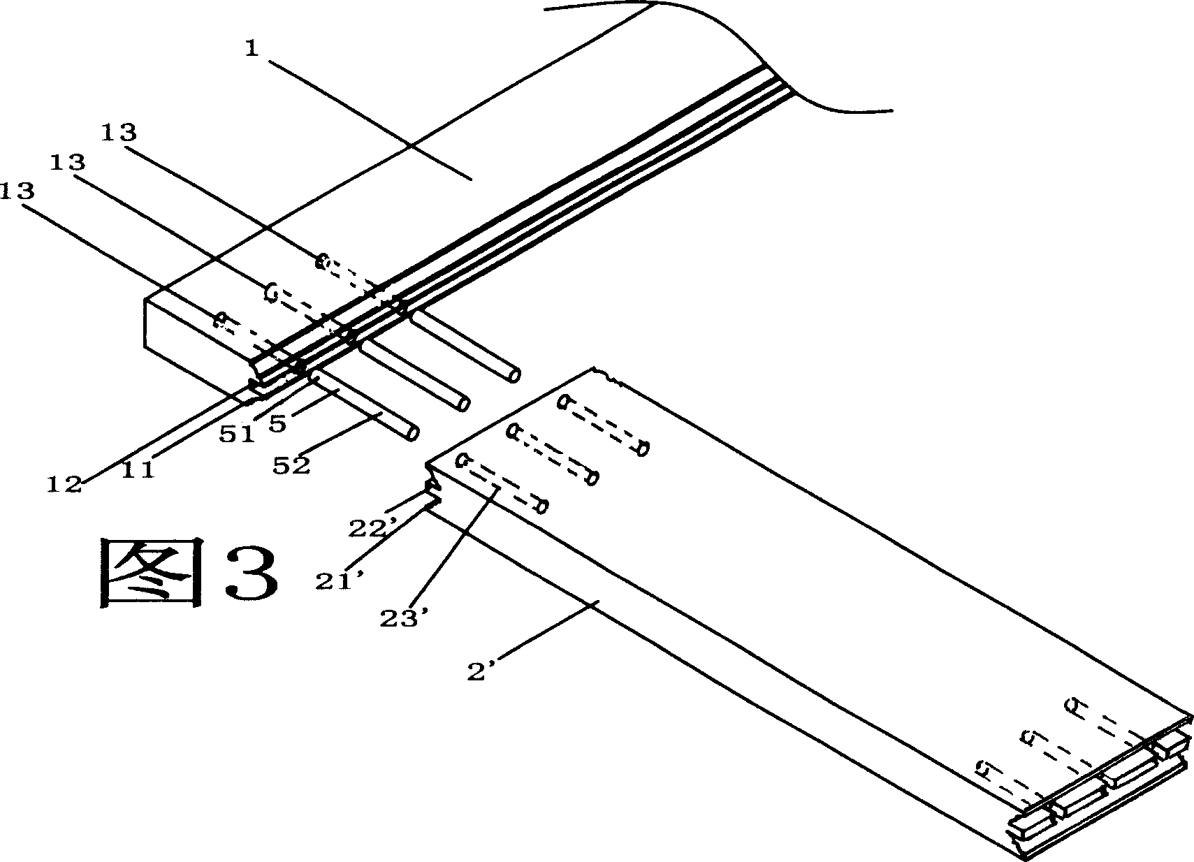
[0025] Please refer to the structure of left door stand 1 shown in Fig. 1, Fig. 3 and Fig. 4, the height of left door stand 1 is 1990 ...
PUM
 Abstract
Description
Claims
Application Information