
Manufacturing method of light conducting board and light conducting board stamper and manufacturing processing of light conducting board

A manufacturing method and technology for a light guide plate, applied in optics, nonlinear optics, instruments, etc., can solve the problems of high cost, low development efficiency, and difficult microstructure, and achieve the effects of simple manufacturing process, low cost, and high efficiency

Inactive Publication Date: 2007-05-23
HONG FU JIN PRECISION IND (SHENZHEN) CO LTD +1
View PDF0 Cites 5 Cited by
  • Summary
  • Abstract
  • Description
  • Claims
  • Application Information

AI Technical Summary

Problems solved by technology

Because the development cycle and production time of the mold and the mold core are long, and at the same time, in the development process of the mold core, it is difficult to process the microstructure corresponding to the dots on the light guide plate, so the development efficiency is low and the cost is too high

Method used


Image

  • Manufacturing method of light conducting board and light conducting board stamper and manufacturing processing of light conducting board
  • Manufacturing method of light conducting board and light conducting board stamper and manufacturing processing of light conducting board
  • Manufacturing method of light conducting board and light conducting board stamper and manufacturing processing of light conducting board

Examples


Embodiment Construction

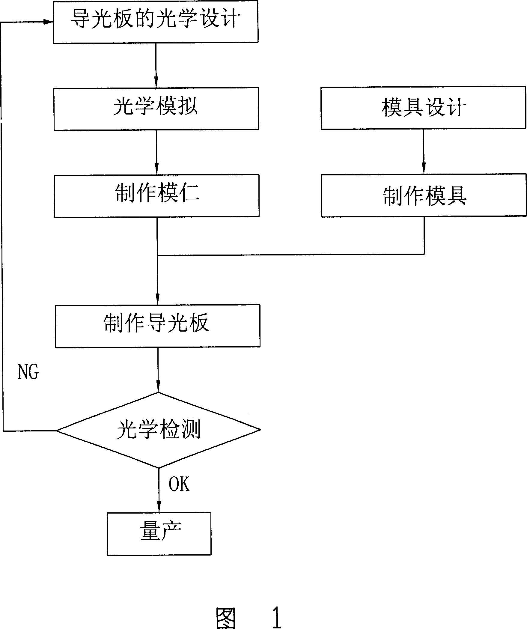
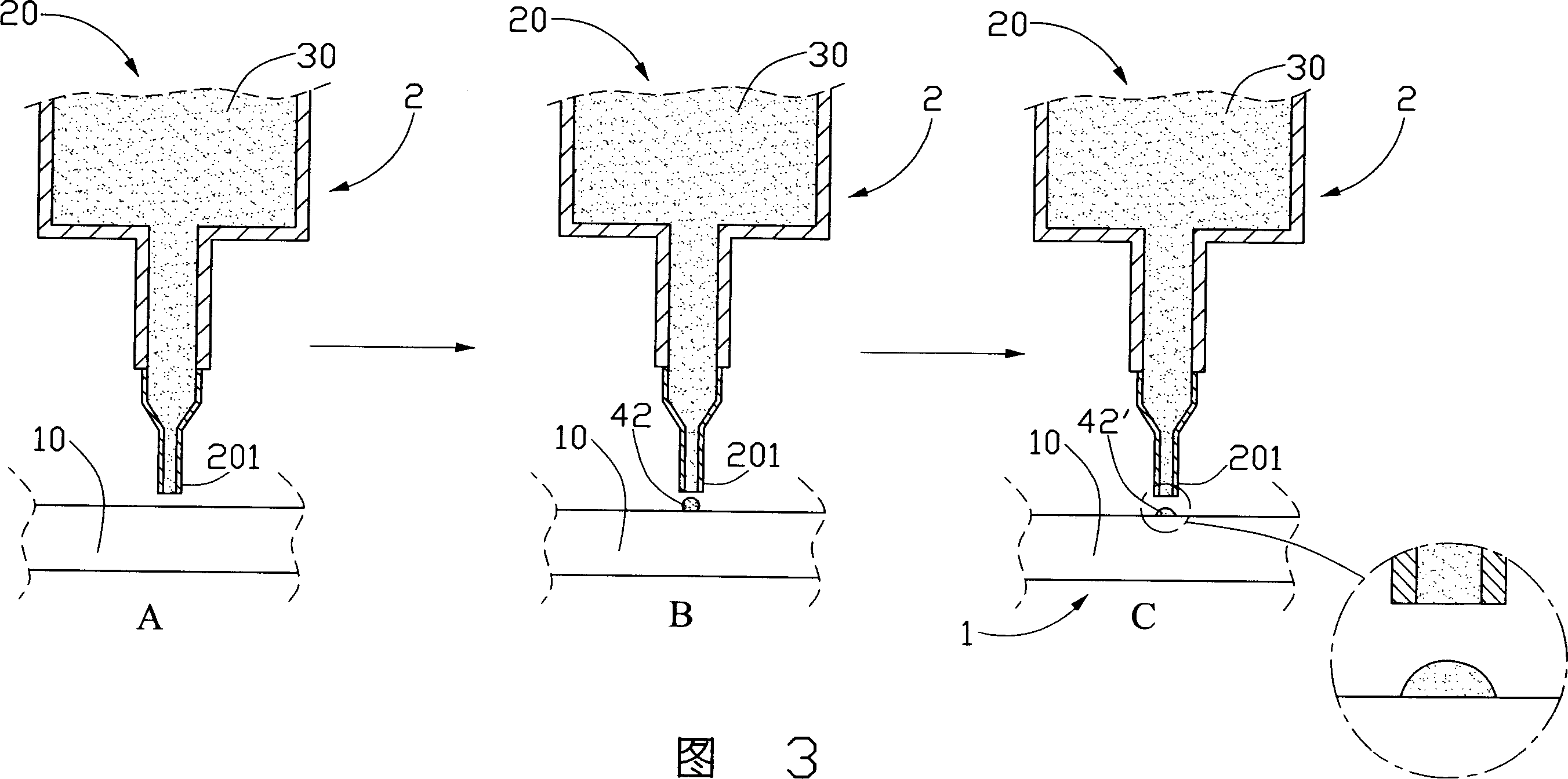
[0019] Please refer to FIG. 2 and FIG. 3 , which are respectively a flow block diagram and a flow diagram of an embodiment of the light guide plate manufacturing method of the present invention.

[0020] The manufacturing method of the light guide plate includes the following steps:

[0021] (1) providing a substrate 10;

[0022] (2) Provide glue dispensing machine 2, this glue dispensing machine 2 comprises a cavity 20 and a syringe 201; Prepare to form the site of network dot, as shown in Figure 3A;

[0023] (3) projecting a certain amount of solution-like curing glue 42 from the syringe 201 at the position where dots are prepared to be formed, so that it is bonded to the substrate 10, as shown in Figure 3B;

[0024] (4) curing the solution-like curing glue 42 bonded on the substrate 10 under certain conditions to obtain a curing glue 42' forming a fixed shape, as shown in Figure 3C;

[0025] (5) Steps (3) and (4) are repeated until all dots on the substrate 10 are comple...


PUM


Abstract

The invention discloses an illuminator manufacturing method, an illuminator-scale manufacturing methods and illuminator manufacturing processes. The illuminator manufacturing method includes the following steps: (1) providing a substrate; (2) providing a point gum machine. The point gum machine includes a capacity and a syringe cavity, the cavity with Yung-curing adhesive solution, syringes positioning of the substrate prepared by the design of the site to form networks; (3) throw a certain amount of solution-curing adhesive from syringes to the prepared positioning of the site to form networks, substrate bonding with it; (4) under certain conditions in curing adhesive substrate solution-curing adhesive; (5) repeat steps (3), (4), until completion of all substrates outlets, which have illuminator.

Description

【Technical field】 [0001] The invention relates to a method for manufacturing a light guide plate, a method for manufacturing a mold core of the light guide plate and a production process of the light guide plate. 【Background technique】 [0002] A liquid crystal display is a passive display device, which does not have luminous properties, and needs to be provided with a backlight module to realize the display function. The light guide plate is an important component in the backlight module, which is used to guide the transmission direction of the light beam emitted from the light source, and convert the line light source or point light source into a surface light source to emit. [0003] In order to improve the uniformity of light emission, generally a plurality of dots are arranged on the surface of the light guide plate, such as micro lenses (Micro Lens), to destroy the total reflection condition of the light beam transmitted inside the light guide plate, and to scatter it ...

Claims


Application Information

Patent Timeline
IPC IPC(8): G02F1/1335
Inventor 岳国汉
Owner HONG FU JIN PRECISION IND (SHENZHEN) CO LTD
Learn More