Gas insulation switch device and oil immersed transformer connection structure

A technology for gas-insulated switches and oil-immersed transformers, which is used in gas-insulated substations, switchgear settings, switchgear, etc., which can solve the problem of increased shaft length, restrictions on small size and light weight, and difficulty in reducing floor space. Quantization and other issues to achieve the effect of reducing the axial length

Active Publication Date: 2007-05-23
JAPAN AE POWER SYST
View PDF4 Cites 6 Cited by
  • Summary
  • Abstract
  • Description
  • Claims
  • Application Information

AI Technical Summary

Problems solved by technology

[0003]However, in the conventional connection structure of the gas insulated switchgear and the oil-immersed transformer, two insulating partitions are required in order to form an intermediate chamber between the two. This intermediate chamber increases the axial length between the gas insulated switchgear and the oil-immersed transformer, making it difficult to reduce the footprint and reduce the size and weight of the equipment.
In contrast, in the connection structure between a gas insulated switchgear and an oil-imm

Method used


Image

  • Gas insulation switch device and oil immersed transformer connection structure
  • Gas insulation switch device and oil immersed transformer connection structure
  • Gas insulation switch device and oil immersed transformer connection structure

Examples


Embodiment Construction

[0032] The best embodiment of the present invention will be described below based on the drawings.

[0033] 18 and 19 are a plan view and a front view showing the connection structure of the gas insulated switchgear of the present invention and the oil-immersed transformer.

[0034] The gas-insulated switchgear 16 containing the main circuit conductors in an airtight container filled with insulating gas is composed of a line-side unit and a transformer-side unit. The line-side unit is connected to one end of the breaker 22 between the circuit breaker On the double main buses 21a, 21b, and at the other end of the breaker 22, there is a bushing 23 connected to the transmission line between the circuit breaker, and the transformer side unit connects one end of the transformer side breaker 24 to the double main bus 21a , 21b, and on the other end side is equipped with a lightning arrester 25 installed as needed, each part of the main circuit conductors of each device through insulatin...


PUM


Abstract

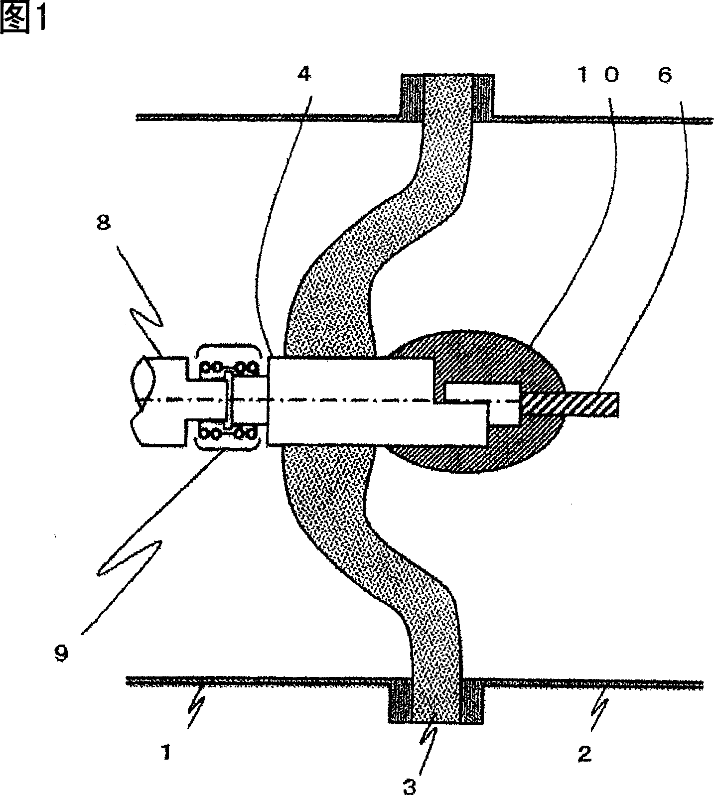
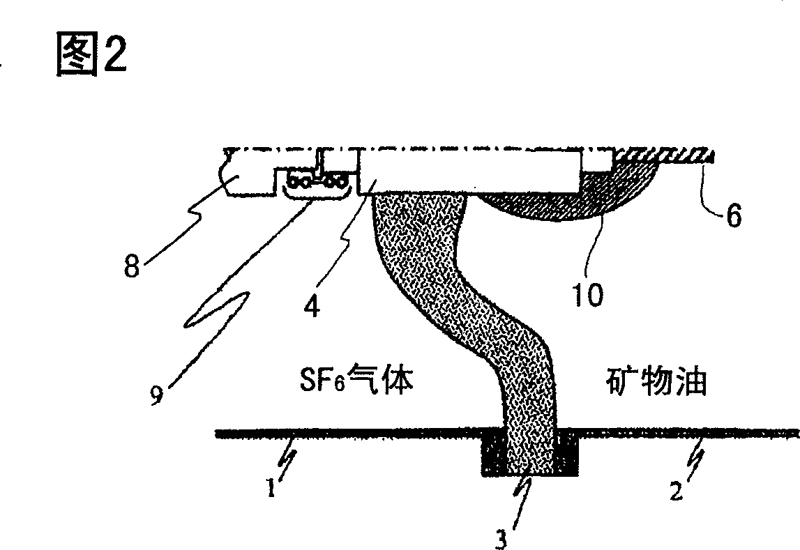
The present invention provides a connecting structure of a gas insulated switchgear and an oil-immersed transformer in which miniaturization and weight reduction are attained by suppressing axial length. One cone shaped insulation spacer 3 dividing insulating gas and insulating oil is arranged between the connection container 1 on a gas insulated switchgear 16 side in which the insulating gas is enclosed and the connection container 2 on an oil-immersed transformer 17 side in which the insulating oil is enclosed. The cone shaped insulating spacer 3 has a cone shape or a cross section shape similar thereto, having one side with projected surface and the other side with recessed surface, and the projected surface side is arranged on the gas insulated switchgear 16 side while the recessed side on the oil-immersed transformer 17 side. A buried conductor 4 for connecting the main circuit conductor 8 on the gas insulated switchgear 16 side to the flexible conductor 6 as the main circuit conductor of the oil-immersed transformer 17 is provided at the center portion of the cone shaped insulating spacer 3.

Description

Technical field [0001] The present invention relates to a connection structure between a gas insulated switchgear and an oil-immersed transformer installed in a substation. Background technique [0002] The gas insulated switchgear installed in the substation is constructed by arranging main circuit conductors in a closed container filled with insulating gas. On the other hand, oil-immersed transformers are constructed in a closed container filled with insulating oil as both For example, use an oil-gas type bushing that horizontally installs the high-voltage output side of the oil-immersed transformer on the side of the oil-immersed transformer, and connects with the gas insulated switchgear. However, if the oil-gas type bushing is used, the shaft length becomes larger, which hinders the reduction of the floor space and the downsizing and lightening of the equipment. Therefore, as a connection structure between a gas insulated switchgear and an oil-immersed transformer, it is kno...

Claims


Application Information

Patent Timeline
IPC IPC(8): H02B13/035H01F27/04
CPCH01H33/021H01H33/08H01H33/28H01H33/55H02B5/06H02B13/035
Inventor 六户敏昭筑紫正范山本直幸山极时生田中丰一八塚裕彦
Owner JAPAN AE POWER SYST
Why Eureka
Try Eureka