Conveyor oven

A conveying device and gas technology, applied in food ovens, household stoves/stoves, kitchen utensils, etc., can solve the problems of unsuitable conveying ovens, no space for enlargement, etc., and achieve the effect of reducing cooking time and increasing rotation rate.

Inactive Publication Date: 2007-05-23
特博切夫技术有限公司
View PDF4 Cites 36 Cited by
  • Summary
  • Abstract
  • Description
  • Claims
  • Application Information

AI Technical Summary

Problems solved by technology

[0008] Conveyor furnaces actually ensure that cooked food can be removed from the furnace at just the right time, but conveyor furnaces are generally not suitable for certain food service establishments such as: fast food restaurants (QSR); Customer-operable ovens at retail locations for retail customers; or retail food service locations with no space for conveyor ovens to scale up, etc.

Method used


Image

  • Conveyor oven
  • Conveyor oven
  • Conveyor oven

Examples


Embodiment Construction

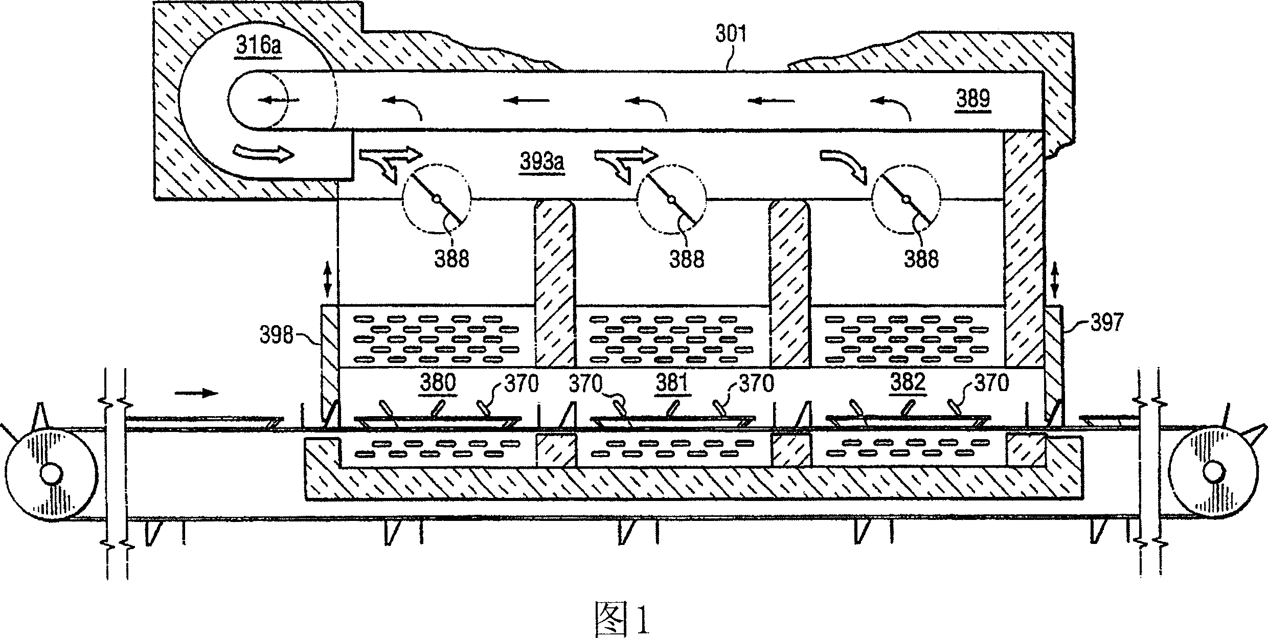
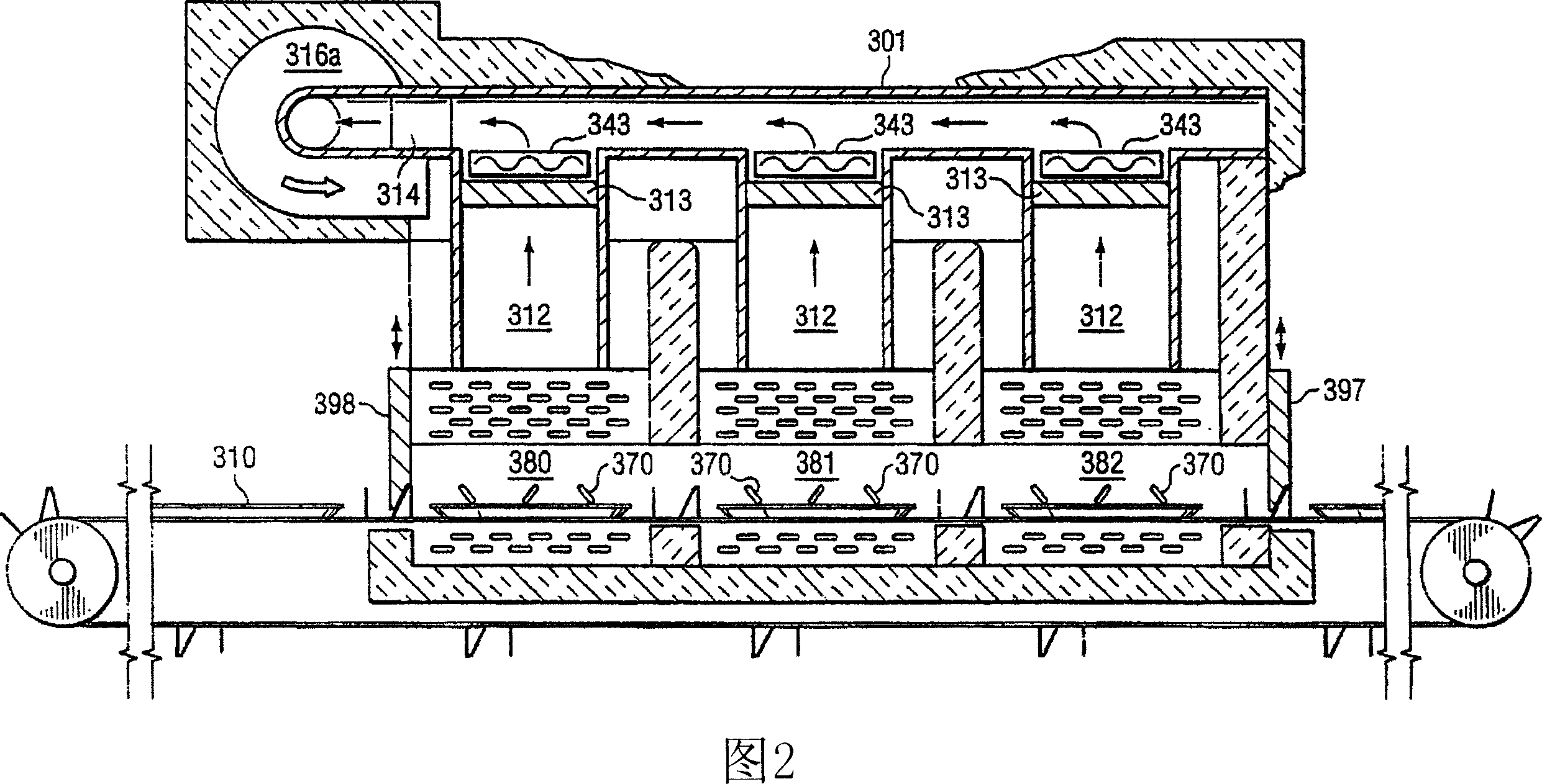
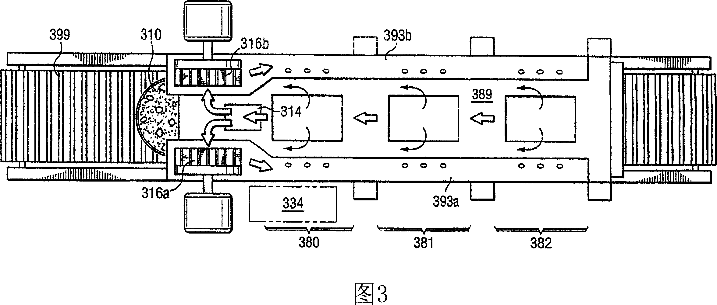
[0032] The oven of the exemplary embodiment is shown as a quick cook commercial conveyor cooking appliance with 3 cooking zones, where although each cooking zone is not necessarily identical, and in fact in some cases it may be desirable for one or more cooking zones to be fabricated as different, but each cooking zone is shown manufactured in the same way. The conveyor furnace of the present invention can be installed in other embodiments because it can be made larger or smaller in size. The term "variable size" here means that additional larger or smaller models can be formed, and that each embodiment or variation can have different size characteristics and use different voltages; various forms of resistance heating means, or Use a heat source such as natural gas, propane, or other heating means to heat the gas.

[0033] As used herein, the terms "magnetron", "magnetron" and "tube" have the same meaning; the terms "slot", "slots" and "antenna" have the same meaning: the ter...


PUM


Abstract

An accelerated cooking or speed cooking conveyor oven with at least one discrete cooking zone. The oven includes a first and a second gas directing member configured to cause the gas from the first gas directing member to collide with the gas fron the second gas directing member upon the upper or lower surface of the food product being conveyed.

Description

[0001] Cross References to Related Applications [0002] This application claims the benefit of U.S. Provisional Patent Application No. 60 / 550,578, filed March 5, 2005, entitled "SPEED COOKING CONVEYOR OVEN"; and filed March 8, 2004, entitled "ANTENNA COVER" US Provisional Patent Application No. 60 / 551,268; and US Provisional Patent Application No. 60 / 615,888, filed October 5, 2004, entitled "CATALYSTFOR SPEED COOKING OVEN". [0003] This application is a continuation-in-part of co-pending U.S. Patent Application Serial No. 10 / 614,479, filed July 7, 2003, entitled "SPEED COOKING OVEN," which claims the benefit of US Provisional Patent Application No. 60 / 394,216 entitled "RAPID COOKING OVEN"; co-pending US Patent Application No. 10 / Continuation-in-Part of Application No. 614,268, which claims the benefit of U.S. Provisional Patent Application No. 60 / 394,216, filed July 5, 2002, entitled "RAPID COOKINGOVEN"; Continuation-in-Part of Co-Pending U.S. Patent Application Serial No. ...

Claims


Application Information

Patent Timeline
Patent Type & Authority Applications(China)
IPC IPC(8): A21B1/08F24C1/00A47J27/00
Inventor 戴维·H·麦克法登
Owner 特博切夫技术有限公司
Why Eureka
Try Eureka