Thermoelectric converter and its manufacturing method
A technology of thermoelectric conversion and manufacturing method, which is applied in the direction of thermoelectric device node lead-out materials, circuits, electrical components, etc., which can solve the problems of difficult to ensure electrical insulation and difficult to improve productivity, and achieve the effect of excellent productivity
- Summary
- Abstract
- Description
- Claims
- Application Information
AI Technical Summary
Problems solved by technology
Method used
Image
Examples
no. 1 Embodiment approach
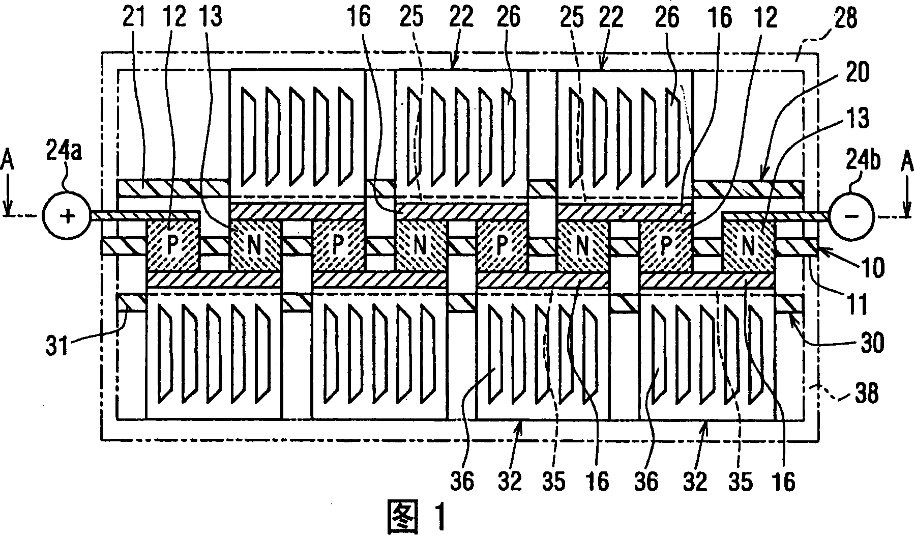
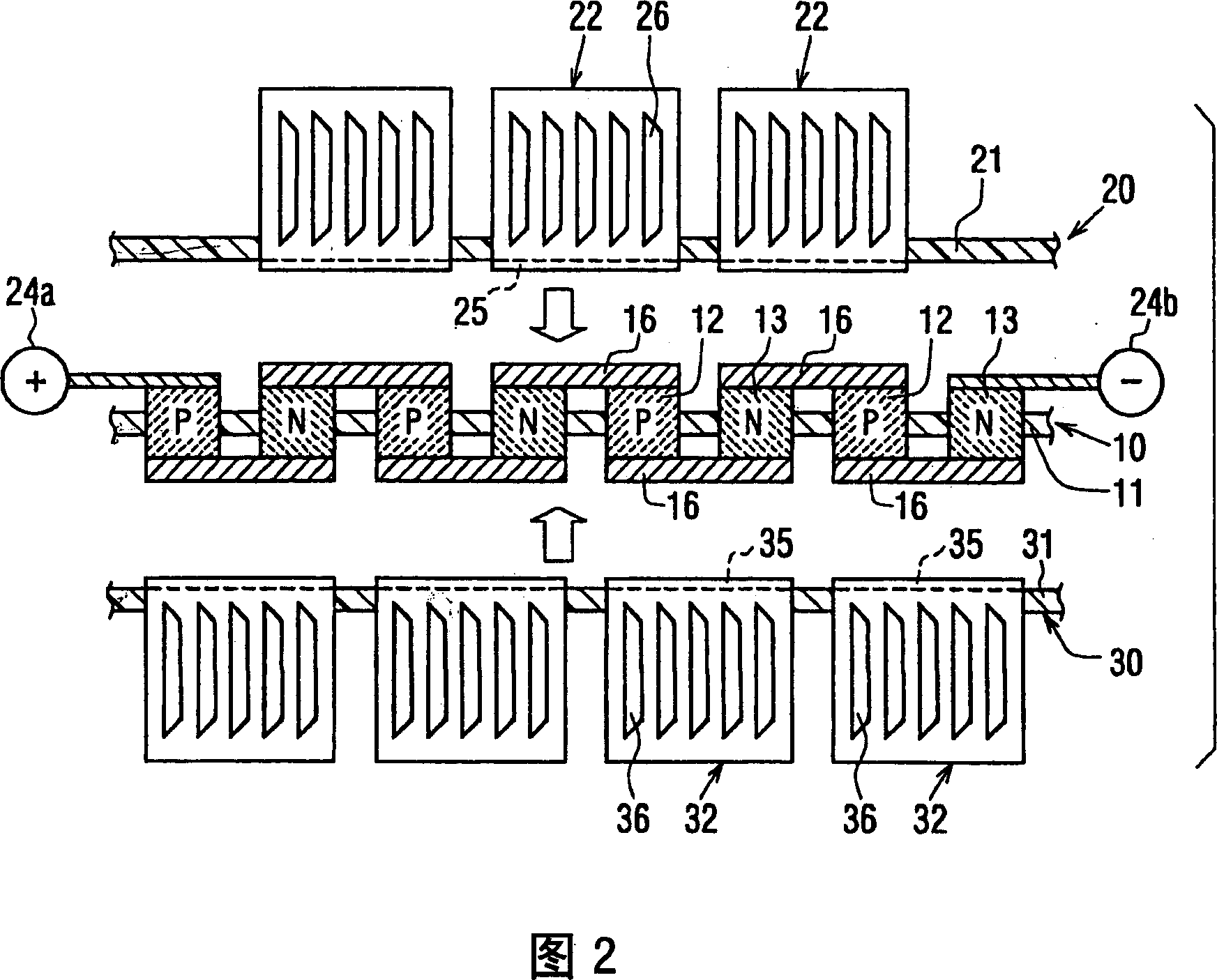
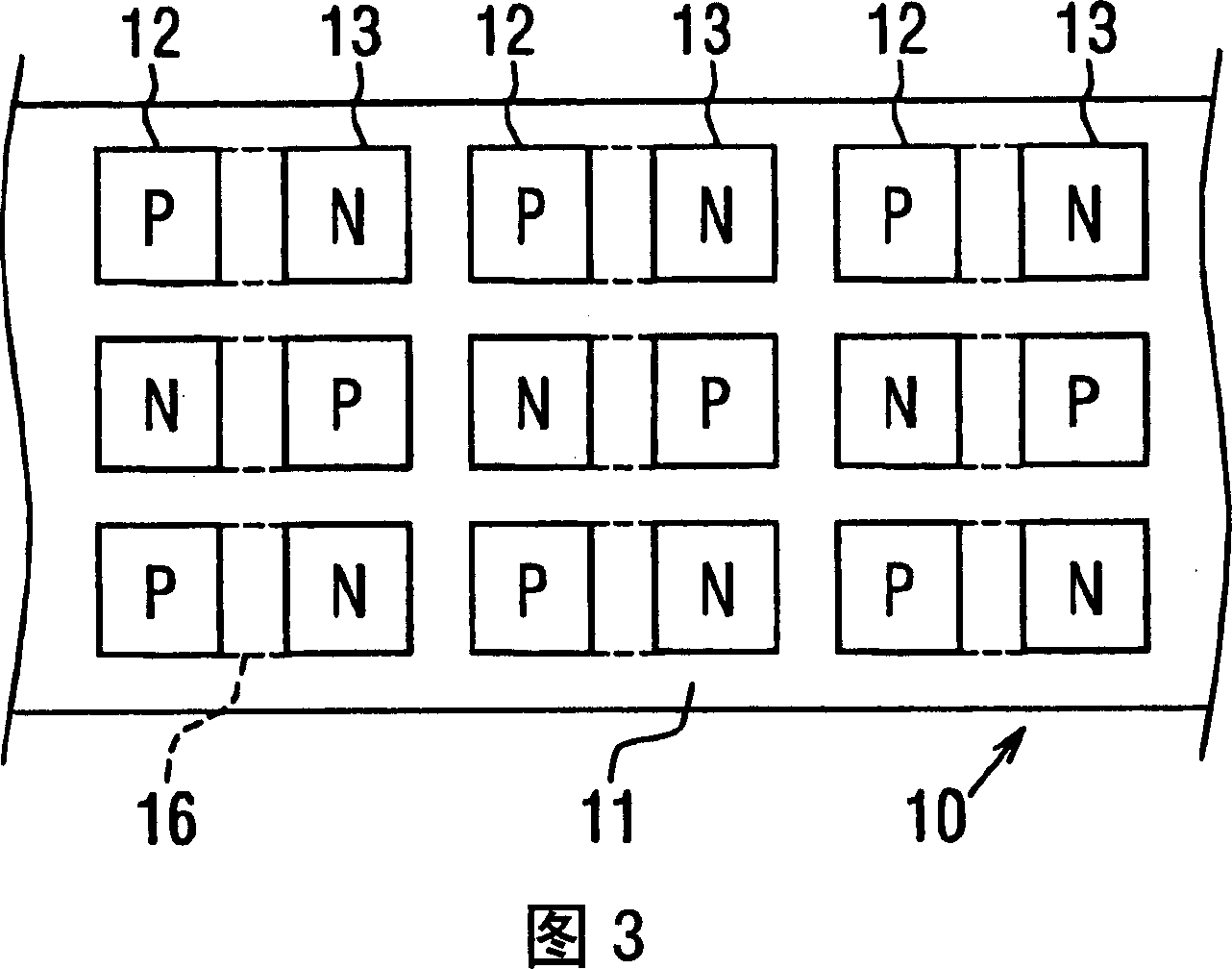
FIG. 1 is a cross-sectional view showing the overall configuration of a thermoelectric conversion device in this embodiment. Figure 2 is an exploded view of this embodiment. Fig. 3 is a partial sectional view showing an arrangement of thermoelectric elements. FIG. 3 shows the view from the arrow A of FIG. 1 . Fig. 4 is a cross-sectional view showing a cross section perpendicular to Fig. 1 .
[0143]
The thermoelectric conversion device is composed of a thermoelectric element substrate 10 , a heat-absorbing electrode substrate 20 , a heat-radiating electrode substrate 30 , and a pair of case members 28 and 38 . This thermoelectric conversion device can be used for cooling air with one and heating air with the other. For example, it can be used as a part of the air conditioner in the passenger compartment.
[0144]
The thermoelectric element substrate 10 is composed of a first insulating substrate 11 which is a holding plate, a plurality of P-type thermoelectric elements ...
no. 2 Embodiment approach
In the above first embodiment, the electrode member 16 is integrally formed with the thermoelectric element substrate 10 . Instead, in the second embodiment shown in FIGS. 5 and 6 , the electrode member 16 is integrally assembled with the heat-absorbing electrode substrate 20 and the heat-dissipating electrode substrate 30 .
[0168]
In FIGS. 5 and 6 , the endothermic electrode substrate 20 has the electrode member 16 joined to the endothermic electrode portion 25 of the first endothermic electrode member 22 . In addition, the heat dissipation electrode substrate 30 has the electrode member 16 bonded to the heat dissipation electrode portion 35 of the first heat dissipation electrode member 32 . Such a structure can be obtained by inserting the first heat-absorbing electrode member 22 and the electrode member 16 into the hole 24 of the second insulating substrate 21 . In addition, it can also be obtained by inserting the first heat radiation electrode member 32 and the elect...
no. 3 Embodiment approach
In this embodiment, electrode substrates 40 are provided between the thermoelectric element substrate 10 and the heat-absorbing electrode substrate 20 and between the thermoelectric element substrate 10 and the heat-dissipating electrode substrate 30 . On the electrode substrate 40, a plurality of electrode members 16 are arranged. The electrode substrate 40 holds a plurality of electrode members 16 .
[0172]
As shown in FIG. 7 , in the electrode substrate 40 , a plurality of electrode members 16 are insert-molded on a fourth insulating substrate 41 made of an insulating material. A plurality of electrode members 16 may be inserted into holes in the fourth insulating substrate 41 and then assembled. In this embodiment, only the thermoelectric elements 12 and 13 are arranged on the thermoelectric element substrate 10 . In this embodiment, the heat-absorbing electrode substrate 20 , the electrode substrate 40 , the thermoelectric element substrate 10 , the electrode substrat...
PUM
| Property | Measurement | Unit |
|---|---|---|
| Plate thickness | aaaaa | aaaaa |
Abstract
Description
Claims
Application Information
 - R&D
- Intellectual Property
- Life Sciences
- Materials
- Tech Scout
- Unparalleled Data Quality
- Higher Quality Content
- 60% Fewer Hallucinations
Browse by: Latest US Patents, China's latest patents, Technical Efficacy Thesaurus, Application Domain, Technology Topic, Popular Technical Reports.
© 2025 PatSnap. All rights reserved.Legal|Privacy policy|Modern Slavery Act Transparency Statement|Sitemap|About US| Contact US: help@patsnap.com


