Filling mold and its building operation method

A technology for building construction and filling molds, which is applied in the direction of buildings, building components, and building structures. performance, shorten the construction period, and improve the feasibility of secondary design

Inactive Publication Date: 2007-05-30
谢孟
View PDF0 Cites 1 Cited by
  • Summary
  • Abstract
  • Description
  • Claims
  • Application Information

AI Technical Summary

Problems solved by technology

[0002] The building molds currently used are generally taken out after pouring and used repeatedly. The corresponding building structure of a mold is also very simple. Since the mold needs to be taken out and used repeatedly, the construction period is relatively long, and due to the needs during use , the template will be clipped
In addition, the buildings made of molds that are commonly used now require a large amount of reinforced concrete, heavy weight of the building itself, long construction period for building structure design, single cross-sectional form of the building structure, large formwork damage, low fire resistance, and high overall cost; and the building The secondary design is poor, the ratio of building materials to its structural performance is low, and the formed concrete structure is a plane structure

Method used


Image

  • Filling mold and its building operation method
  • Filling mold and its building operation method
  • Filling mold and its building operation method

Examples


Embodiment 1

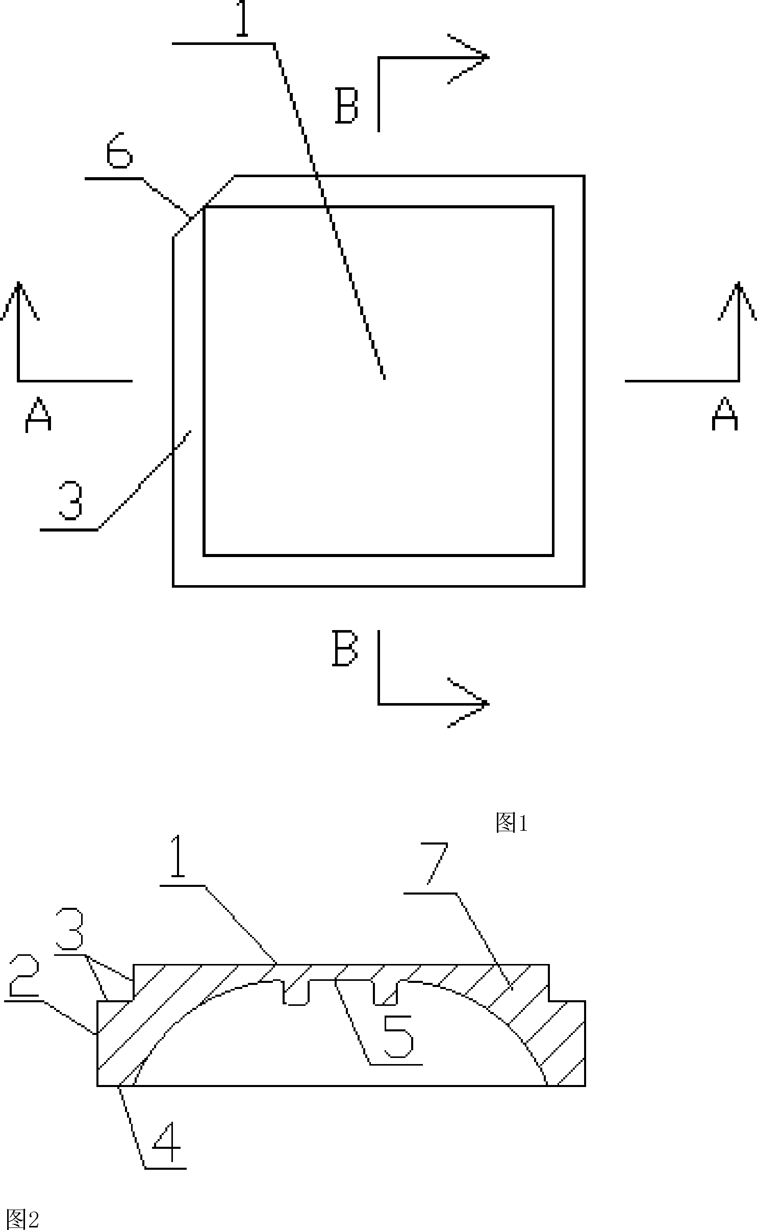
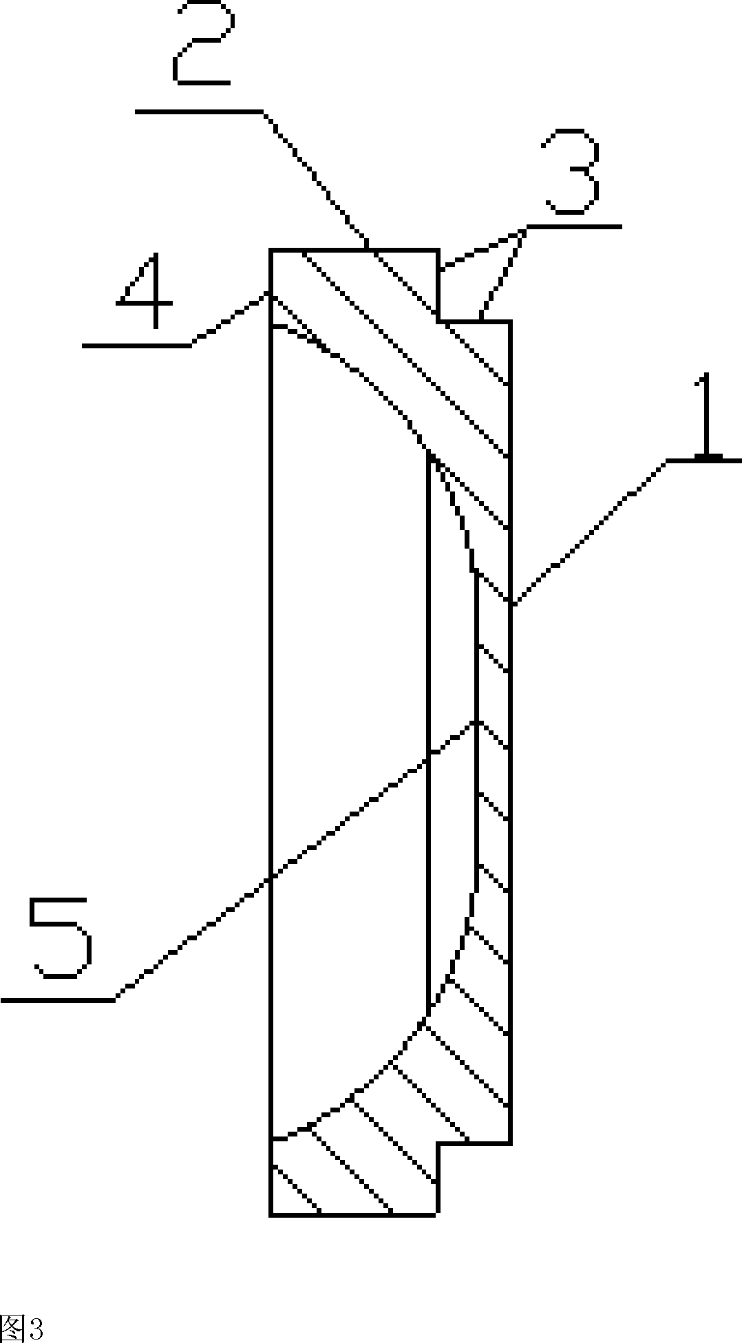
[0034] Embodiment 1: the structure of filling mold is shown in Fig. 1, Fig. 2 and Fig. 3, and the top surface of mold box 7 is die face 1, and die face 1 is the rectangular plane of long 50cm, wide 50cm, the edge of die face 1 and The upper edge of the mold side 2 has a concave platform 3, the plane of the concave platform 3 is a rectangle with a length of 60 cm and a width of 60 cm, and the height of the mold box 7 is 15 cm; The included angles of the planes of the platform 3 are right angles, and the inner cavity of the bottom surface of the mold box 7 is the mold inner surface 5, which is a concave curved surface as shown in Fig. 1 . There is a chamfer 6 on the concave table 3 (all 4 corners can be processed into a chamfer, and in this example, one corner is selected as a chamfer), and the material used for filling the mold is industrial waste phosphogypsum or desulfurization in this example plaster.

Embodiment 2

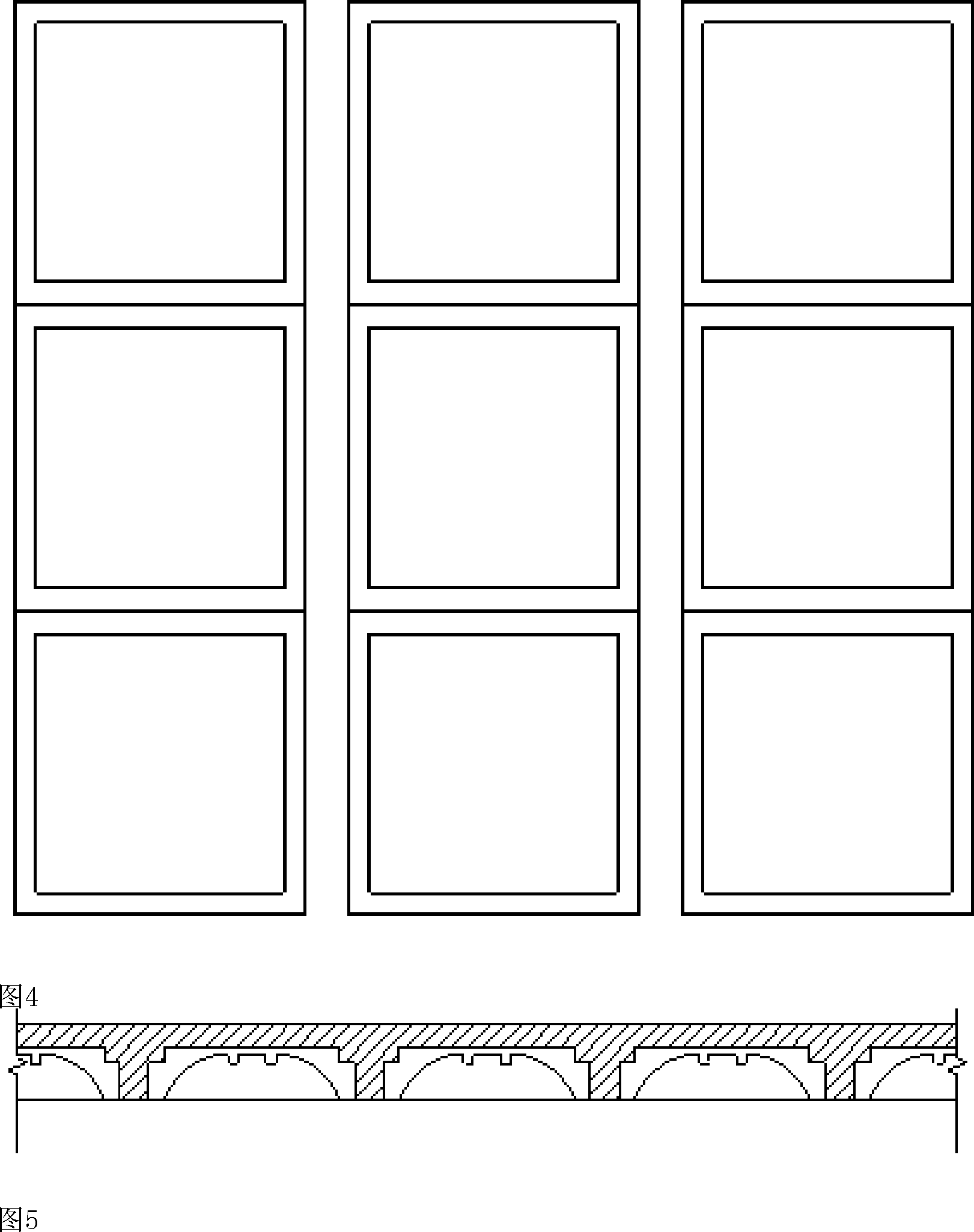
[0035] Embodiment 2: the building structure obtained by the method of filling the mold in the building floor construction as shown in Figure 4, Figure 5 and Figure 6, the bottom surface of the mold 4 is downward, the mold boxes 7 are arranged in a single layer, and the two mold boxes 7 in the horizontal direction are arranged in a single layer. The space between them is arranged with gaps, the gap distance is 7cm, and the two longitudinal mold boxes 7 are closely arranged (there is no gap in the middle); the hollow floor slab formed by injecting reinforced concrete forms a main T-shaped section in the horizontal direction and a secondary T-shaped section in the vertical direction. .

Embodiment 3

[0036] Embodiment 3: The building structure obtained by the method of filling the mold in the construction of the building floor slab is shown in Figure 7 and Figure 8. The mold boxes 7 are arranged in a single layer, and the bottom surface of the mold 4 is upward, and sealed with a thin plate. Between the two mold boxes 7 in the horizontal direction There is a gap arrangement between them, the gap distance is 6cm, and there is a gap arrangement between the two vertical mold boxes 7, the gap distance is 8cm; the hollow floor slab formed by injecting reinforced concrete forms a two-way mouth-shaped section.


PUM


Abstract

The invention discloses a filling mode and the building construction method. The top of mold box (7) is mole face (1) and there is concave platform between the edge of mold face (1) and the side face (2) of mold. The bottom face of mold box (7) is inner hollow and inner face of mold (5). The mold box (7) is arranged at the prepared position and cast. The mold box is stayed in the cast building. The filling mode can shorten the construction period and the period of structure design; lessen the self gravity of structure and the dosage of mold plate. It can lessen the loss of construction mold plate, decrease the steel quantity for structure, improve the fire-resistance performance of building and decrease the whole cost of structure. It can make the building structure diversification, optimize the mechanical property and improve the secondary-design feasibility of building.

Description

technical field [0001] The invention relates to a building material and its construction method, in particular to a building filling form and its building construction method Background technique [0002] The building molds currently used are generally taken out after pouring and used repeatedly. The corresponding building structure of a mold is also very simple. Since the mold needs to be taken out and used repeatedly, the construction period is relatively long, and due to the needs during use , the template will be clipped. In addition, the buildings made of molds that are commonly used now require a large amount of reinforced concrete, heavy weight of the building itself, long construction period for building structure design, single cross-sectional form of the building structure, large formwork damage, low fire resistance, and high overall cost; and the building The secondary design is poor, the ratio of building materials to its structural performance is low, and the f...

Claims


Application Information

Patent Timeline
Patent Type & Authority Applications(China)
IPC IPC(8): E04G15/06E04B5/16E04B5/18E04C1/00
Inventor 谢孟
Owner 谢孟
Why Eureka
Try Eureka